Installation – Warner Electric MCS2000-PSDRV2 User Manual
Page 4
4
Warner Electric • 800-825-9050
P-2010-7 • 819-0525
Installation
Mounting
Select a location that will allow for sufficient air
movement around the control.
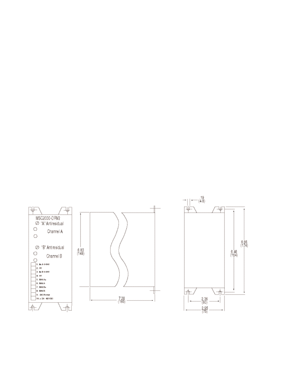
Overall Dimensions: 6.85 x 2.95 x 7.28 inches
(174 x 75 x 185 mm).
Note: Unit must be mounted vertically to have
best possible cooling effect.
o 1.
Using the dimensional data from Figure 1,
drill and tap 4 mounting holes for either
4.5 mm screws or #10 screws on the panel
or mounting surface the drive will be
mounted to.
o 2.
Using either 4.5 mm or #10 screws, mount
the unit to the panel or mounting surface.
Tighten screws sufficiently so that unit will
Figure 1 Mounting Dimensions
Driver Outline and Mounting Dimensions
not come loose during normal machine
operation or vibration.
Note: 0 Volt terminals in control are tied to
control housing. A good ground is required
between the control and the panel or
mounting surface.
o 3.
After unit is mounted and secured, make
sure that spacing is sufficient around the
housing and that at least a clearance of at
least 2.00 inches (50.8 mm) for the front
panel wiring plug to facilitate wiring unit
and plugging connector to control.
o 4.
Double check all mounting before
proceeding to the wiring section.