System troubleshooting – Warner Electric MCS2000-PSDRV2 User Manual
Page 17
17
Warner Electric • 800-825-9050
P-2010-7 • 819-0525
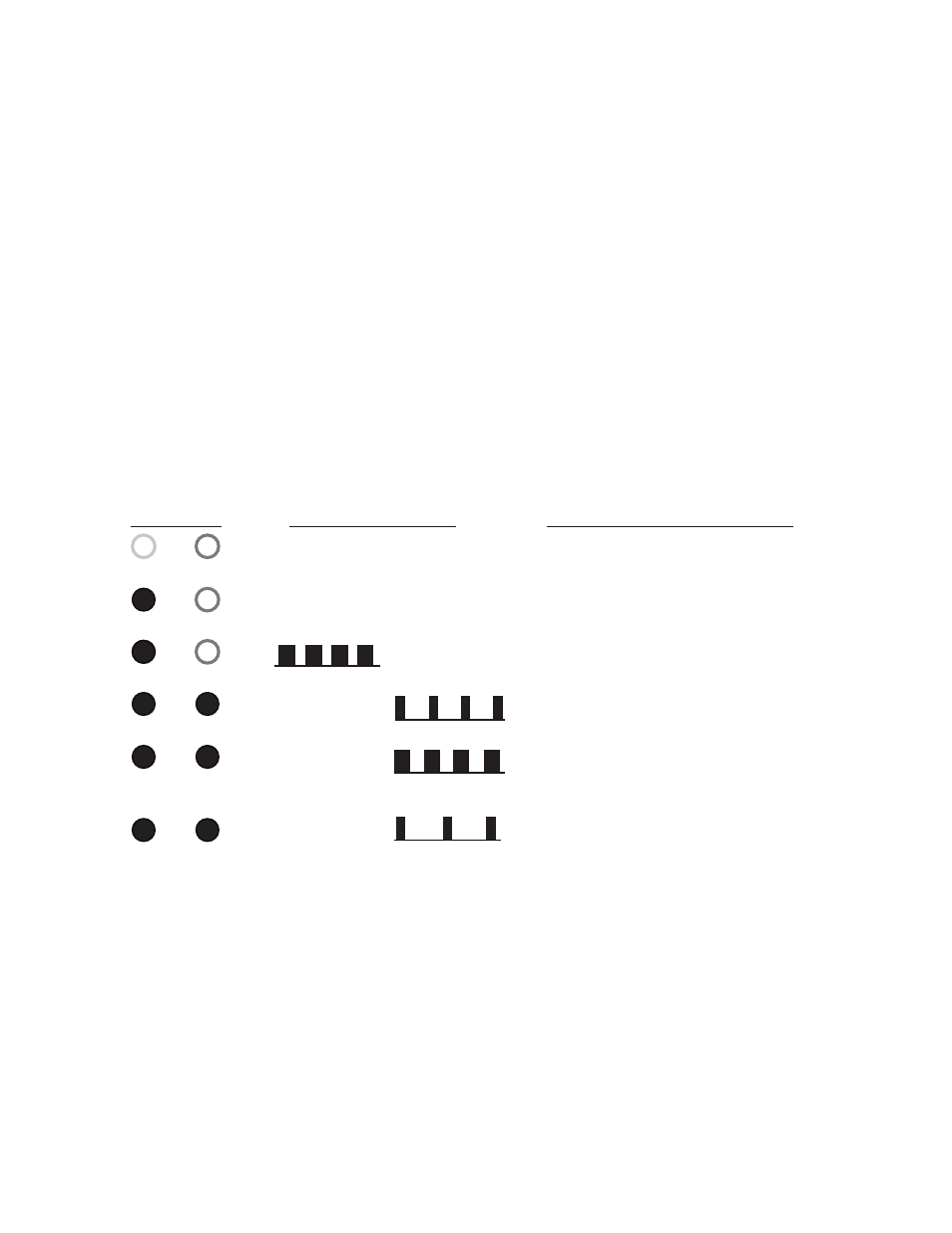
LED’s
Green
Green
Red
Red
ON
ON
ON
ON
OFF
OFF
OFF
OFF
LED Operation
Functional Description
MCS2000-PSDRV2 is Powered Off
MCS2000-PSDRV2 is “ON” and ready
MCS2000-PSDRV2 is in anti-residual mode
MCS2000-PSDRV2 Overcurrent enabled
Limited to 60 sec maximum at full output.
MCS2000-PSDRV2 Overcurrent limit
has gone past 60 sec. Output has reduced
back to 24 volts.
MCS2000-PSDRV2 Normal operation but
overcurrent is not available as it is still in
limit mode and will reset on time out.
0.5 Sec ON/2.5 sec OFF
1 Sec ON/1 Sec OFF
0.5 Sec ON/1.5 Sec OFF
1.5 Sec ON/0.5 Sec OFF
Figure 6 LED Indicator Operations and Descriptions – Normal Operation
Note: Each Channel “A” and “B” can be operated independently, so one channel can have one
set of indications while the second channel can have a completely different set of indications.
This will be dependent on how controller is set to operate the MCS2000- PSDRV2 Driver.
System Troubleshooting
Troubleshooting the MCS2000-PSDRV2 Dual
Channel/Dual Voltage Driver is fairly straight
forward. There are certain basic checks that can
be made using a digital meter. All readings taken
on the MCS2000-PSDRV2 will be either DC
voltages or DC currents, or AC line voltage. A
meter sufficient to measure up to 100 VDC and
10 Amps DC and 300 VAC will be suitable for
taking any of the measurements deemed
necessary.
Additionally, the MCS2000-PSDRV2 offers a
certain amount of diagnostics built into the
unit via the “GREEN” and “RED” LED’s for
troubleshooting purposes.
As with any electronic device, care should be
taken when installing, wiring and commissioning
the unit. Failure to do so may damage or destroy
the driver and void the warranty.
The following diagnostic indications are possible
with the two indicator LED’s on the face of the
controller.