Warner Electric MCS2000-PSDRV2 User Manual
Page 6
6
Warner Electric • 800-825-9050
P-2010-7 • 819-0525
Note: Since the MCS2000-CTDA and
MCS2000-CTLC controllers have
25 pin DB connectors with cables
wiring is made via the cable.
Care must be taken to insure the correct wires
are connected and none of the other wires
contact or short out. It is recommended that
unused wires be cut off and taped so that
shorting and grounding out does not occur.
Note: Refer to the MCS2000-CTDA or
MCS2000-CTLC Manual for exact wire
functions and designations.
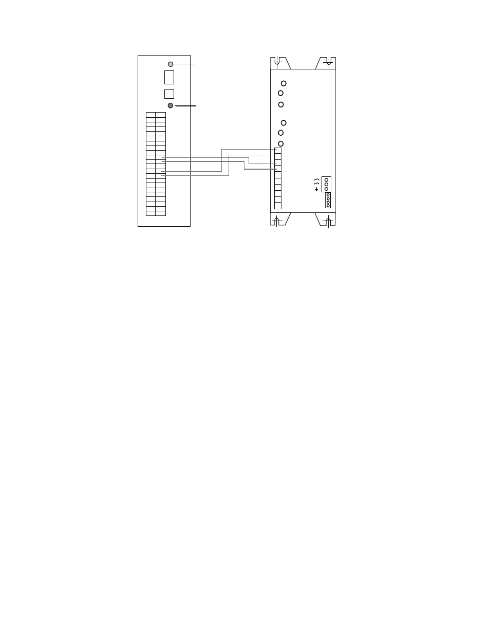
Refer to Figure 3 for wiring hook-ups.
(green)
(red)
MSC2000-PSDRV2
“A” Antiresidual
Channel A
“B” Antiresidual
Channel B
1
2
3
4
5
6
7
8
9
10
InA 0-10V
0-V
InB 0-10V
0V
Brk A+
Brk A-
Brk B+
Brk B-
-DC Pwr
+24-48V
+24V
+24V
0V
0V
MCS2000-ECA Controller
MCS2000-PSDRV2 Driver
Figure 2 MCS2000-ECA to MCS2000-PSDRV2
Note: Wiring is shown for both channels. If only one channel is required, then follow wiring for channel “A”.
Wiring to the MCS2000-CT’S Controllers
- UNIBRAKE NEMA 4 (6 pages)
- UNIBRAKE (8 pages)
- ARC 2000 (16 pages)
- ARC Clutch_ZRC Top Load (18 pages)
- ZRC Clutch_ARC Top Load (18 pages)
- Dairy Cap Chuck (24 pages)
- Dairy Capping Headsets (10 pages)
- Autogap 475 & 650 (4 pages)
- Brushholder Installation (2 pages)
- Autogap 825-1225 (2 pages)
- Electro-Packs EP-170, 250, 400, 500, 825, 1000, 1525 (20 pages)
- Electro-Brake 375, 475, 650, 825, 1000, 1225 (20 pages)
- Electro-Clutch EC-375, EC-475, EC-650, EC-825, EC-1000, EC-1225 (20 pages)
- 5300-101-001 Collector Ring (2 pages)
- 5301-101-010 Collector Ring (2 pages)
- Brushholder Assembly and Mounting Dimensions (2 pages)
- SF_PB 400 (2 pages)
- SF_PB 250 (2 pages)
- Autogap 825-1525 (4 pages)
- Electro-Module EM-50, EM-100, EM-180, EM-210, EM-215 (22 pages)
- FB-375, 475, 650 (14 pages)
- 5200-101-012 Conduit Box Kit (4 pages)
- 5200-101-011 Conduit Box Kit (4 pages)
- 5200-101-010 Conduit Box Kit (4 pages)
- Recommended Electrical Installation Procedure for Warner Electric Clutches and Brakes (2 pages)
- EP-400 Vertical Mounting (2 pages)
- EP-250 Vertical Mounting (2 pages)
- Autogap 500 (4 pages)
- ER 825 and 1225 Normal Duty (16 pages)
- ER 825 and 1225 Heavy Duty (14 pages)
- ERS Electrically Released Brakes (6 pages)
- AT Brakes & Clutches Complete Brake Repair – On the Shaft, Sizes 25, 55, 115 (4 pages)
- AT Brakes (6 pages)
- AT Brake–Major Service Repair Instructions for Sizes 25, 55, 115 (9 pages)
- AT Clutch – Major Service Sizes 25, 55, 115 (12 pages)
- 5162-101-002 Conduit Box Kit (6 pages)
- Electrically Released Permanent Magnet Clutch Compatible Modules (4 pages)
- Electrically Released Motor Brake Module for EM-MBFB and EUM-MBFB (6 pages)
- Electrically Released Brake Module For EM-FBB and EUM-FBB (4 pages)
- Electrically Released Brake ER-375, ER-475, ER-650 (12 pages)
- Autogap 825-1525 Special Heavy Duty (4 pages)
- 5370-101-042 Conduit Box Kit (4 pages)
- Preassembled Clutch_Electrically Released Brake Module (7 pages)
- EUM-50_EUM-100_EUM-180_EUM-210_EUM-215 (16 pages)
- 5370-101-045 Conduit Box Kit (5 pages)