Warner Electric ERD Size 060 to 300 User Manual
Page 7
Warner Electric Europe • +33 (0)2 41 21 24 24
P-2060-WE • 2/13 5
Switch Characteristics
Protection
IP 40
Temperature:
-40°C / +85°C
Switching power
5A - 250 VAC
Switch connection
6.3
Hand release kit
Only for use with VAR02
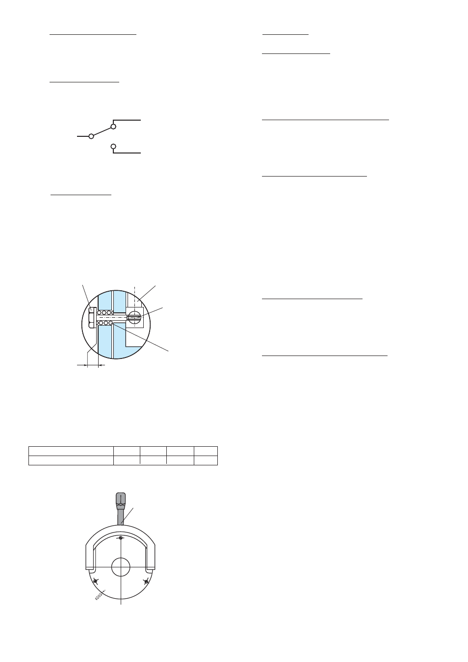
Fitting (Fig. 5 and 6)
Check that the brake is correctly set to the
nominal airgap.
Fit the bolts into the lever and through the inductor,
posi tion the springs in the moving armature, then
tighten nut as shown in Fig. 5, respecting dimension
X, see table 5.
6.4
Accessories
Dust Cover – (555)
If you are using the brake in a clean environment
or it the surrounding atmosphere is loaded with
dust or humidity we recommend the use of a
dust cover.
Friction Disc Carrier – (312 or 315)
Sizes 005 and 010 as standard are supplied with
a syn thetic version. On request, metallic version
for sizes 005 and 010 are also available.
Thick Friction Flange – (341)
If the mounting surface does not meet the
following specifications:
• cast iron or steel surface
• hardness 150 HB
• roughness 3,2 Ra (125 microinches)
• flatness 0,05 mm
then a thin or thick friction flange has to
be used.
Thin Friction Flange – (340)
This flange offers mounting at the inner diameter.
With the thin friction flange the mounting screws
are located at the outside.
Mounting Screw Kit – (913 or 914)
The short mounting screw kit supplied with
the thick flange is for mounting on the external
diameter threaded holes.
The long mounting screw kit supplied with the
thin flange is for mounting through the thin flange
on external diame ter or if ordered separately for
direct mounting without flange.
Removable
Handle
Fig. 6
ERD Size
005
010
020
035
Dim. X (+0,2/0 mm)
1
1
1
1,5
Table 5
Black
Red
Blue
Control position
2 positions
Washerscrew
Hand release
Axle
Spring
X
Fig. 5