Warner Electric ERD Size 060 to 300 User Manual
Page 6
4 Warner Electric Europe • +33 (0)2 41 21 24 24
P-2060-WE • 2/13
6
Options
6.1
Torque adjustment
Torque adjustment is only possible on
VAR02 (~ 50% of nominal torque).
Brakes are supplied adjusted to nominal torque.
Principle of torque reduction:
On VAR 02 (table 3), undo the adjustment ring
located at the rear of the inductor (see chapter 7).
Standard version
6.2
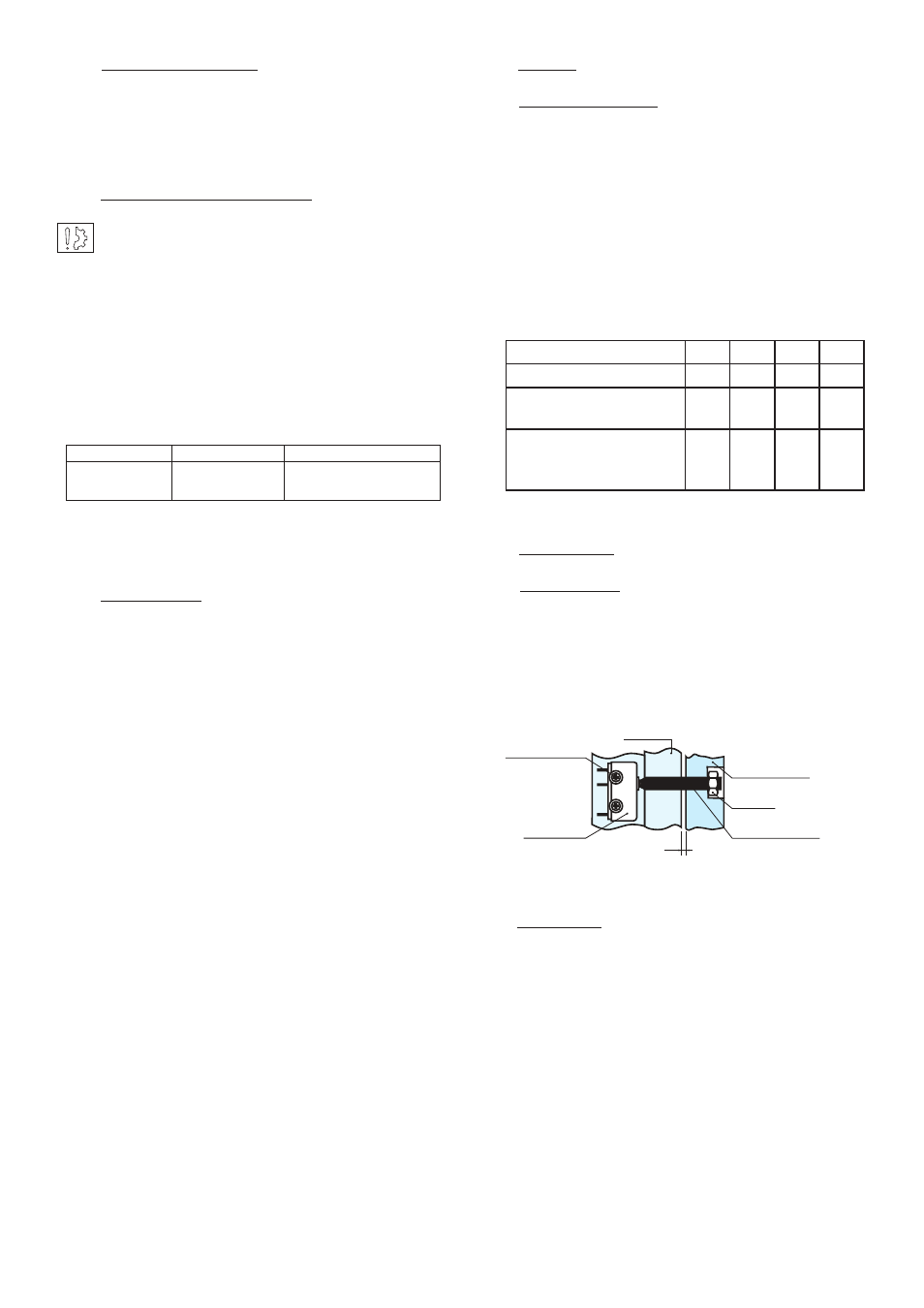
Detection kit
Fitting (Fig. 4)
Check that the brake is correctly set to the
nominal airgap. Tighten the M6 bolts in the
moving armature then fit the nut (see Fig. 4), then
fix the sensor using the M3 bolts and washers.
Adjustment
Insert a shim 0,15 mm thick near to the bolt
between the face of the inductor and moving
armature. Switch the device on, tighten the bolt
to contact with the sensor until the switch point is
obtained then lock the bolt using the nut.
Check correct operation by making several
successive starts and releases.
5
Electrical connection
ERD brakes have to be supplied with direct
current and are factory fitted with 400 mm long
wires. The polarity does not affect operation.
5.1
Important recommendations
All works on the electrical connections have to
be made with power off.
Ensure compliance with the nominal supply
voltage (inade quate supply causes a reduction
in the starting distance).
The connecting wires should be of sufficient
diameter to prevent voltage drops between the
source and equipment supplied.
Tolerance for the supply voltage to the brake
terminals +5% / -10% (NF C 79-300).
5.2
Power supply
We
advise the use of
Warner Electric CBC 140-
1, CBC 140-2 or CBC 140-5 supply units (with
overexcitation and holding voltage)
The supply and switching method has a great
influence on the response time. Response times
shown in our cat alogues are for a supply at
nominal voltage with DC side switching.
In the event of AC switching, the braking
response time may be multiplied by 6.
To get very short brake release and braking
times, we advise the CBC 140-5 (please ask):
•
With overexcitation on brake release, the start
time can be divided by 3 (according to the
supply voltage)
• Adjusting the hold voltage to 50% of
the nominal voltage reduces the brake
engagement time and its temperature rise
Warner Electric supply units provide protection
for coils and circuits. Where a brake is used
without our supply units, with switching on the
DC, it is essential for the coil to be protected
against surges by a varistor fitted in parallel.
I (A) / L (m)
0 to 10 m
from 10 to 20 m
0 to 3 (A)
1,5 mm
2
1,5 mm
2
3 to 6 (A)
1,5 mm
2
2,5 mm
2
Table 3 (VAR 02)
Fig. 4
M5 screw
Nut
Moving
Armature
Magnet
Switch
Screw
washer M3
X
ERD Size
005
010
020
035
Nominal torque (Nm)
5
10
20
35
Max. number of turns
(adjustment ring)
4
4
4
4
Theoretical reduction in
torque for 1 turn of the
nut (Nm)
0,5
1,3
1,25
2,4