Warner Electric ERD Size 060 to 300 User Manual
Page 5
Warner Electric Europe • +33 (0)2 41 21 24 24
P-2060-WE • 2/13 3
3.2
Handling
Avoid any impacts on the equipment so as not
to alter their performance.
Never carry the equipment by the electrical
supply cable.
3.2
Installing
NB : ERD Size 005 to 035 brakes are supplied
in kit form. The pre-assembled inductor is
supplied with airgap adjusted, see chapter 7
(appendix).
Customer shall maintain:
1. Squareness of flange mounting face
with shaft within 0,15 mm T.I.R. measured at
mounting shaft.
2. Concentricity of flange mounting with
mounting shaft within 0,15 mm T.I.R.
3. The mounting surface should be made of
steel or cast iron, square to the shaft with a
surface finish of 5 to 8 µm or a fine turned finish
over the contact area
If a friction flange (340) or (341) is supplied, fix it
first.
Put the key into the shaft then slide the hub
(515) onto the shaft and secure it axially by
suitable means.
Slide the friction disc (312) or (315) onto the
hub.
If a hand release kit is supplied, it is advisable to
mount it onto the pre-assembled inductor before
the inductor is fitted, see chapter 6.
Fit the pre-assembled inductor (108), remove
the transport shims (551) and fix using the fixing
bolts (913) or (914). Noting carefully the tightening
torque, see table 1.
Secure the bolts using a LOCTITE 270 type
thermoplas tic liquid. If a dust cover (555) is
supplied, carefully slide it onto the equipment
before fitting.
4
Maintenance
4.1
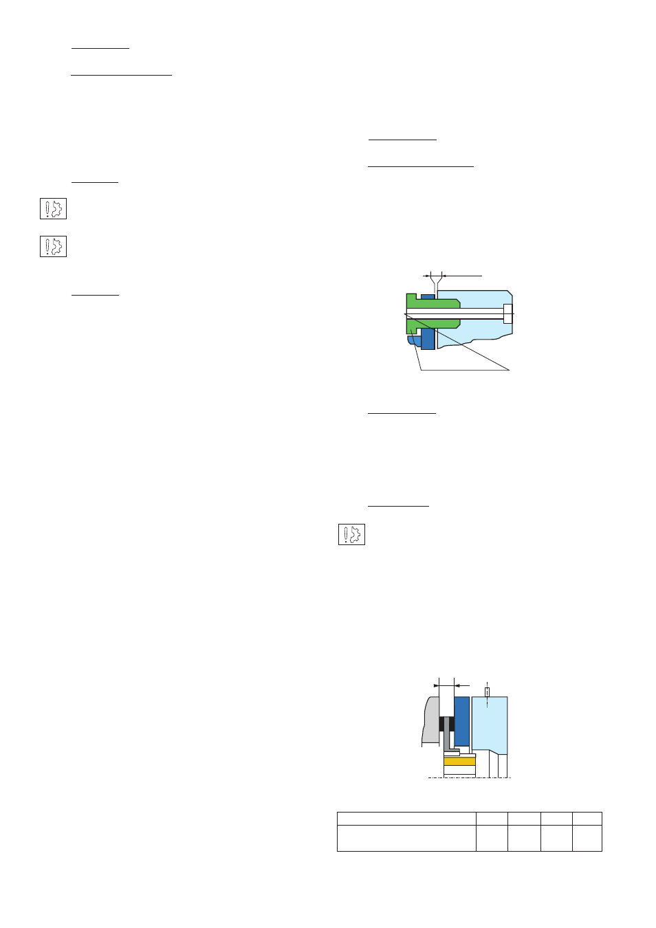
Adjusting the airgap
To reset the airgap (figure 1), undo the adjustment
bolts and adjust to obtain the necessary gap
size, (see table 1). Measure the airgap at several
points. Cycle the brake a num ber of times then
re-check.
4.2
Maintenance
Wear in the friction material causes an increase
in the air gap. Before reaching the maximum
airgap, see table 1, it is necessary adjust it, see
Fig. 1.
4.3
Spare parts
After several adjustments, variable according
to size and use, it is necessary to replace the
friction disc, see Fig. 2 and table 2.
To replace the friction disc (312) or (315), undo the
fixing bolts (913) or (914) then take off the pre-
assembled induc tor (108) and then the friction
disc. Put the new friction disc into position then
refit the pre-assembled inductor and re adjust the
airgap, see paragraph 4.1.
Fig. 1
ERD size
005 010 020 035
E min (mm) w/o hand
5,5
5,2
7,8
8,5
release
Table 2
Adjusting screw
Airgap
Fig. 2
E
3
Installation
3.1
Transport / storage
These units are delivered in packaging that
guarantees a 6 months storage period whether
transported by land, by air, or by sea to any
destination excepting tropical countries.
Switch the equipment on and confirm that the
friction disc rotates freely.
Cycle the brake a number of times and re-check
the value of the airgap. If the airgap is incorrect,
refer to chapter 4 (maintenance).