Warner Electric ERD Size 060 to 300 User Manual
Page 13
Warner Electric Europe • +33 (0)2 41 21 24 24
P-2060-WE • 2/13 5
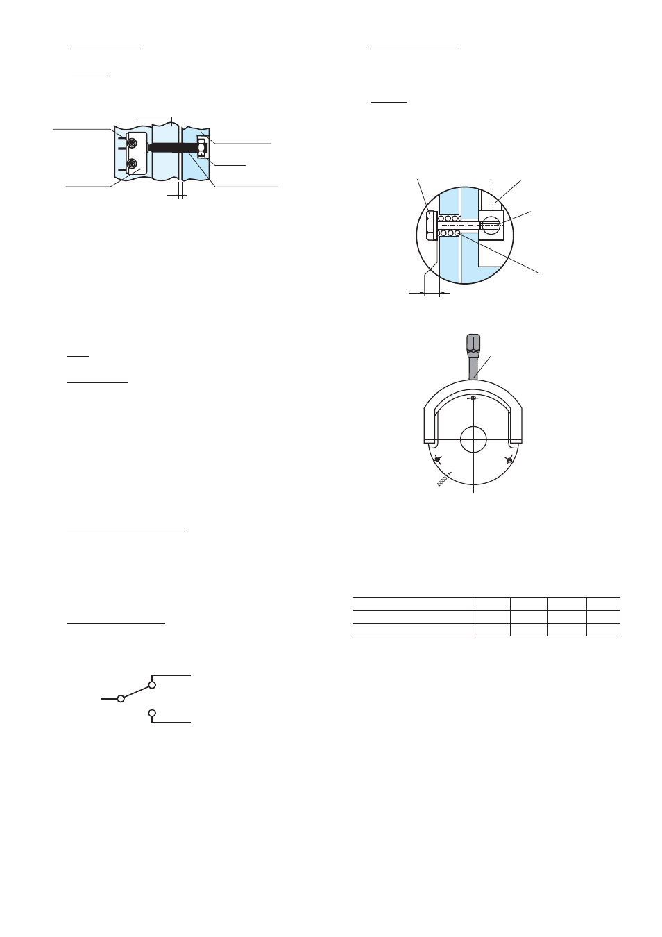
6.2
Detection kit
Fitting
Check that the brake is correctly set to the
nominal airgap. Tighten the M5 bolts in the moving
armature then fit the nut (see figure 4), then fix the
sensor using the M5 bolts and washers.
NB : The M3 fixing bolts are self tapping.
Adjustment
Insert a shim 0,15 mm thick near to the bolt
between the face of the inductor and moving
armature. Switch the device on, tighten the bolt
to contact with the sensor until the switch point
is obtained then lock the bolt using the nut.
Check correct operation by making several
successive starts and releases.
Switch characteristics
Protection
IP 65
Temperature
-40°C / +120°C
Cable
3 x 0,75 mm
Switching power: 8A-250VAC / 6A - 380 VAC
Switch connection
M5 screw
Nut
Moving
Armature
Magnet
Switch
Screw
washer M3
X
6.3
Hand release kit
Only for use with VAR02
Fitting: (Fig 5 and 6)
Check that the brake is correctly set to the
nominal airgap.
Fit the spindles in the lever, the springs in the
moving arma ture, then the bolts and washers as
shown in figure 5, res pecting dimension X (See
table 4)
ERD size
060
100
170
300
ERDD HT size
120
200
340
600
Dim. X (+0,2/0 mm)
1
1
1
1,5
Table 4
Fig. 4
Black
Red
Blue
Control position
2 positions
Removable
Handle
Fig. 6
Washerscrew
Hand release
Axle
Spring
X
Fig. 5