Warner Electric AT Clutch – Major Service Sizes 25, 55, 115 User Manual
Page 7
7
Warner Electric •
800-825-9050
819-0324
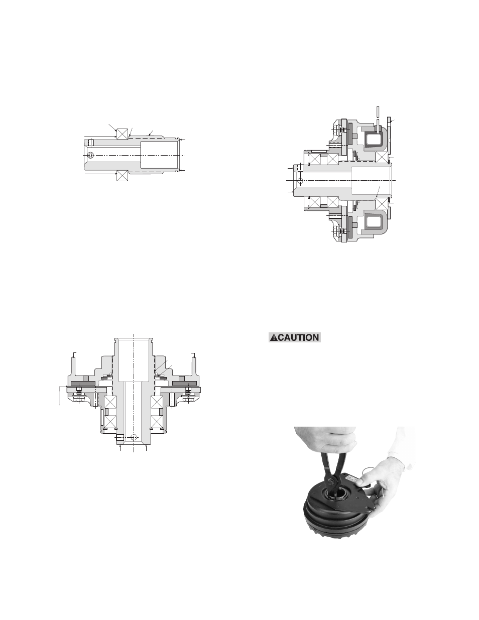
Note: The Armature Assembly must rotate
freely on the hub. Inspect to insure that
the inner bearing is still firmly located
against the hub shoulder as previously
shown in (Figure 1). When inspecting,
place unit firmly on flat surface with
exposed hub end up.
Figure 1
23. Install the rotor assembly onto the hub (Item
6) making sure that the spline teeth are
aligned. When the Autogap detent ring (item
8-3) contacts the spline outside diameter,
press by hand evenly on the rotor until the
friction disc contacts the armature. Release
pressure. Support as shown. The rotor will
spring back approximately .050”. The
Autogap is now set. When the hub is rotat-
ed by hand, the armature and the friction
disc must not touch. (See Figure 6)
Figure 6
24. Press the field assembly onto the hub by
pushing the inner race of the bearing
while supporting on the hub. Apply force
until the inner race of the bearing is located
flush against the shoulder adjacent to the
spline. (See Figure 7)
Figure 7
Install the retaining ring (Item 11) on the hub
with snap ring pliers.
Rotate the hub. No interference between
the shell and rotor is allowable.
When installing or remov-
ing this or other retaining rings, be sure
to hold the ring with one hand so it will
not spring away, endangering personnel
and property, should the pliers lose their
grip on the ring. Safety glasses should
always be worn when installing or
removing retaining rings.
Support
Support
Press
Force
Bearing
Hub
Shoulder
Hub
Press
Force
SUPPORT
MAXIMUM
.050 AIRGAP
ALL AROUND
PUSH
PUSH
SPLINE
DETENT
RING
SUPPORT
SUPPORT
PRESS
FORCE
SHELL
ASSEMBLY
PRESS
FORCE
SUPPORT
UNTIL FLUSH