Warner Electric AT Clutch – Major Service Sizes 25, 55, 115 User Manual
Page 2
2
Warner Electric •
800-825-9050
819-0324
Contents
Introduction . . . . . . . . . . . . . . . . . . . . . . . . . . . . 2
Warranty. . . . . . . . . . . . . . . . . . . . . . . back cover
Failure to follow these
instructions may result in product damage,
equipment damage, and serious or fatal
injury to personnel.
AT Clutch – Major Service
A major rebuild of an AT clutch can be accom-
plished by following these instructions to
replace the parts furnished in the appropriate
Warner Electric clutch rebuild kit. Part numbers
and component descriptions for these kits are
found on page 11 of this manual. Item numbers
in these instructions refer to clutch components
shown on page 10, exploded view. Proceed as
follows:
1.
Turn off all power to the clutch.
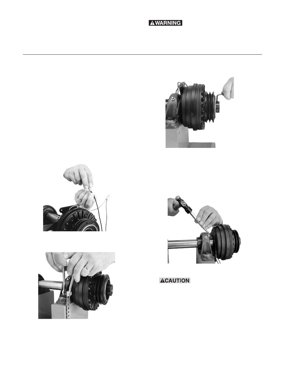
2.
Disconnect the coil wires from the incoming
control unit wires.
3.
Disconnect the field anti-rotation pin or field
restraining arm (Item 16).
4.
Loosen the setscrews (Item 6) which hold
the clutch to its shaft.
5.
Remove the clutch from its shaft by pulling
and/or gently tapping the hub with a ham-
mer and drift.
Note: Do not hit the outer portion of the
clutch outboard of the hub as this may
severely damage it.
6.
Remove the retainer ring (Item 11).
When removing this or
other retaining rings, be sure to hold the
retaining ring with one hand so it will not
spring away and endanger personnel and
property should the pliers lose their grip
on the ring. Safety glasses should always
be worn when installing or removing
retaining rings.