Warner Electric AT Clutch – Major Service Sizes 25, 55, 115 User Manual
Page 6
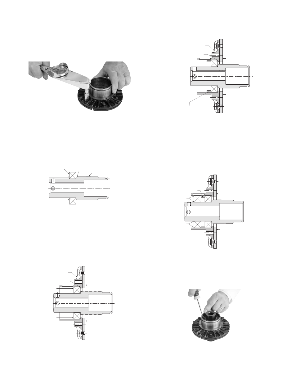
20. Install the spacer (Item 5) as shown in
Figure 3.
Figure 3
21. Press the outer bearing (Item 4) into place
by applying force evenly against the bearing
outer and inner races simultaneously while
supporting the armature face. Continue
pressing until the outer race firmly locates
against the spacer. See Figure 4.
Figure 4
22. Install the external and internal retaining
rings (Items 2 and 3) adjacent to the outer
bearing. (See Figure 5)
Figure 5
6
Warner Electric •
800-825-9050
819-0324
Tighten the cap screws to the appropriate
torque for your size unit:
Size
Torque
25
29-35 in.-lbs.
55-115
60-84 in.-lbs.
18. Install the inner adapter bearing (Item 4)
onto the hub, (Item 6) by pressing on the
inner race of the bearing. With the end of
the hub supported as shown in Figure 1,
press the bearing until its inner race locates
against the hub shoulder.
Figure 1
19. Press the hub and bearing into the Adapter
Assembly until the outer race of the bearing
locates against the shoulder of the adapter
hub. Note that the force is to be exerted
on the outer race. Support the armature
face as shown in Figure 2.
Figure 2
Support
Support
Press
Force
Bearing
Hub
Shoulder
Hub
Press
Force
Armature
Assembly
Support
Support
Adapter
Shoulder
Press Force
Press Force
Armature
Assembly
Support
Adapter
Shoulder
Support
Spacer
Spacer
Support
Press Force
Evenly Applied
Press Force
Evenly Applied
Support