Warner Electric AT Clutch – Major Service Sizes 25, 55, 115 User Manual
Page 4
4
Warner Electric •
800-825-9050
819-0324
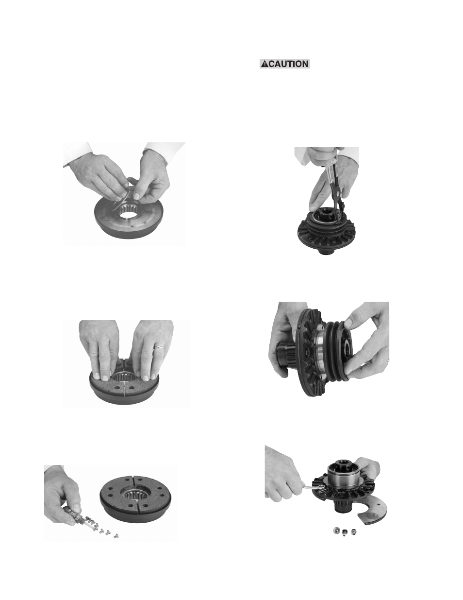
13. Install replacement Autogap components as
follows: Remove plate (item 8-2-size 115
only), and detent ring (item 8-3) to expose
wave spring (item 8-4). Remove and replace
wave spring (item 8-4). Reinstall the detent
ring and plate (items 8-3 and 8-2). Note:
The detent ring lip must point away from
the friction disc. Install the wave spring
with its split 180° from the split in the
detent ring.
14. Clean all foreign matter from rotor mounting
surface. Install the new friction disc seg-
ments (Item 8-1) with new screws (Item 8-5)
included with the kit. Note: Use only the
screws included with the kit as any others
may damage the clutch.
Apply a drop of Loctite grade AA or equiva-
lent to each screw prior to installation.
Tighten each screw to 18-22 in. lb. torque.
15. Remove the snap ring (Item 3) from the
armature hub assembly.
When installing or remov-
ing this or other retaining rings, be sure
to hold the ring with one hand so it will
not spring away, endangering personnel
and property should the pliers lose their
grip on the ring. Safety glasses should
always be worn when installing or
removing retaining rings.
Remove the pulley, sheave, or sprocket if it
interferes with removing the cap screws
(Item 7-2).
16. Disassemble the armature hub assembly by
removing cap screws (Item 7-2), lock wash-
ers (Item 7-3) and armature segment (Item
7-1).