Coil data – Warner Electric ER 825 and 1225 Normal Duty User Manual
Page 9
9
Warner Electric • 800-825-9050
P-250 • 819-0122
When the brake armature cannot be visually
observed during brake voltage adjustment, an
ohmmeter can be used to determine when the
armature disengages. One ohmmeter lead should
be attached to the armature itself, in a manor not
to obstruct the movement of the armature. The
release point can be determined as follows:
Put machine in a safe condition
so that when voltage is applied to control
and switch closures are made the brake does
not rotate and machine does not run.
1. The brake is engaged when the armature
contacts the magnet, causing very low resistance
(less than one Ohm).
Section V
Ohmmeter Procedure to Detect Armature Release
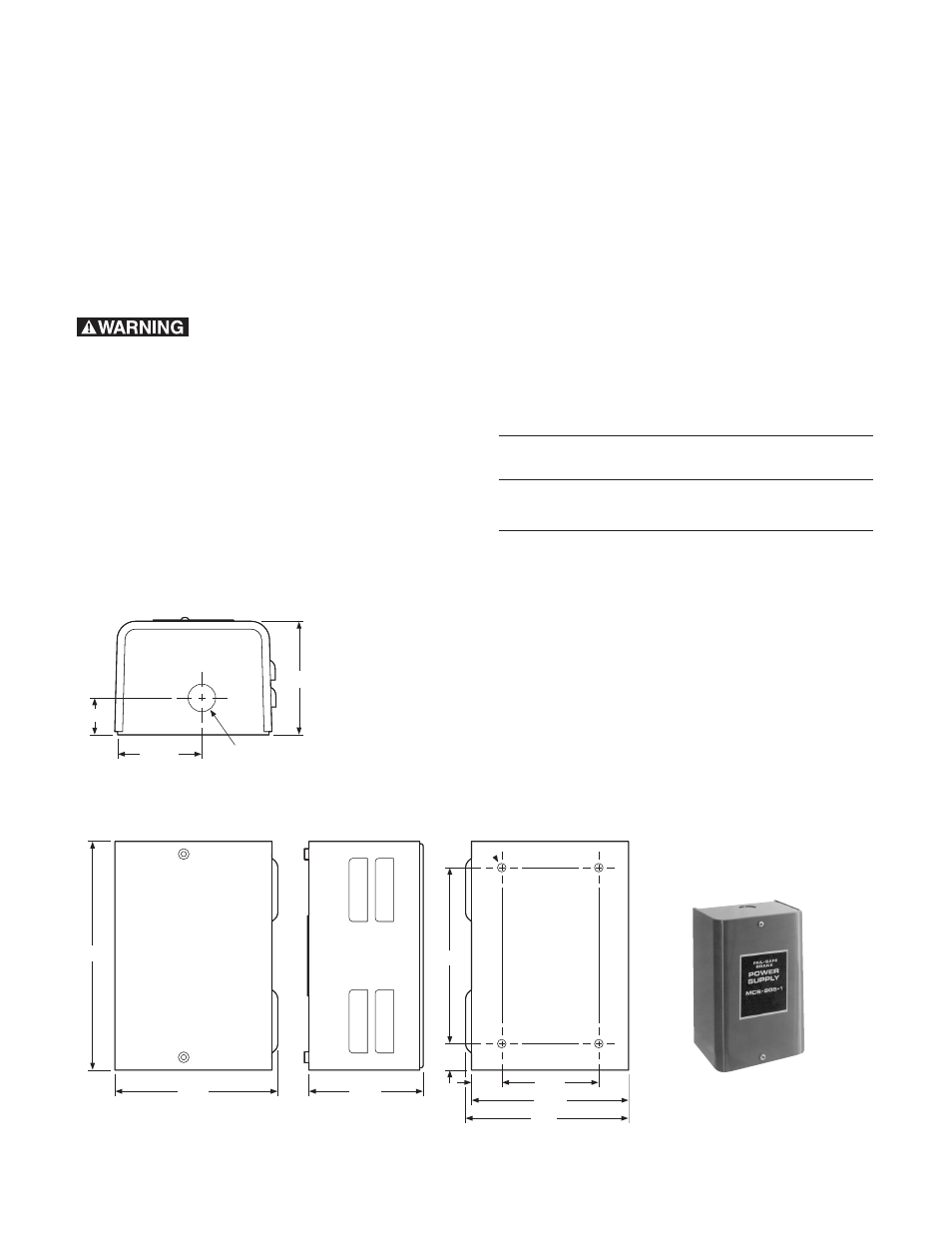
MCS-805-1 and MCS-805-2 Power Supply
Dimensional Drawings and Mounting Provisions
2. The brake is disengaged (released) when the
Ohmmeter indicates higher resistance (usually
greater than one Ohm—may be as high as 10,000
Ohms).
The difference between ohmmeter readings 1 and
2 must be large enough to reliably indicate
armature engagement or disengagement. Reliable
readings can usually be obtained from a brake
mounted on a shaft running on anti-friction
bearings.
Coil Data
Unit
Current Draw (amp)
Resistance (ohms)
Size
at 60 Volts D.C.
at 20°C (±10%)
ER-825
.308
195
ER-1225
.256
235
0.875 Diameter Knockouts
for 0.50 Conduit
Both Ends Typical
0.28 Diameter
(4) Mtg Holes
Clearance for
.25" Screw
TOP AND BOTTOM
FRONT
SIDE
BACK
3.44
2.625
1.125
7.125
5.0
3.44
0.56
6.0
4.81
5.0
3.75
0.53