Warner Electric ER 825 and 1225 Normal Duty User Manual
Page 3
3
Warner Electric • 800-825-9050
P-250 • 819-0122
Sizes ER-825 and ER-1225 with Pin
Drive Armatures Installation Instructions
Basic Mechanical Considerations
Electrically released brakes require special
mounting considerations. Please review the
items listed below prior to starting installation
contained in steps 1-12.
A. If the brake magnet is to be mounted to
a surface of magnetic material, isolate
the brake approximately 1/2 inch from
the surface with a plate or spacer of
non-magnetic material.
B. If a choice of armature shaft material exists,
this should also be non-magnetic. Materials
such as type 302-304 stainless have been
used very successfully.
C. In order to minimize stray flux, the unit should
be exposed as much as possible or, if
enclosed, it should be placed in a housing of
non-magnetic material such as stainless steel
or aluminum.
D.
must be exercised when the
armature is moved close to the magnet
assembly since the permanent magnets
create a very strong attractive force. Injury
may result if fingers are in between the
armature and magnet when the gap is 1/2"
or less.
E.
Foreign Materials: If units are used on
machinery where fine, abrasive dust, chips,
oil or grit are dispelled into the atmosphere,
a protective screen over the unit may be
necessary.
Where units are used near
gear boxes or transmissions requiring
frequent lubrication, means should be
provided to protect the friction surfaces
from oil and grease to prevent serious
loss of torque.
Applications requiring a
vertical shaft mounting must be reviewed
and approved by Warner Electric
Applications Engineering.
Section I
Assembly
Step 1:
Check to insure that the magnet and its
mounting surface are clean and free from
burrs.
Step 2: Bolt the magnet in place with capscrews
and lockwashers.
Note: The magnet pilot diameter must be
concentric to the shaft within .010 inch T.I.R.
The magnet mounting surface must be square
with the shaft within .006 inch T.I.R. measured
at the bolt circle.
Step 3: Assemble the armature to the armature
hub with the autogap mounting accessory as
follows:
New armatures shipped from
the factory are flat to within .005 inch and
this flatness must be retained to maintain full
torque. Any attempt to pry the armature
loose from the magnet will distort the
armature. When adjusting the armature
position, apply any required force only to the
hub, not to the outer edge of the armature.
Also, use care when handling the armature
as dropping may also cause distortion.
Note: Failure to set control voltage using the
step by step procedures in this manual may
cause overheating and premature failure.
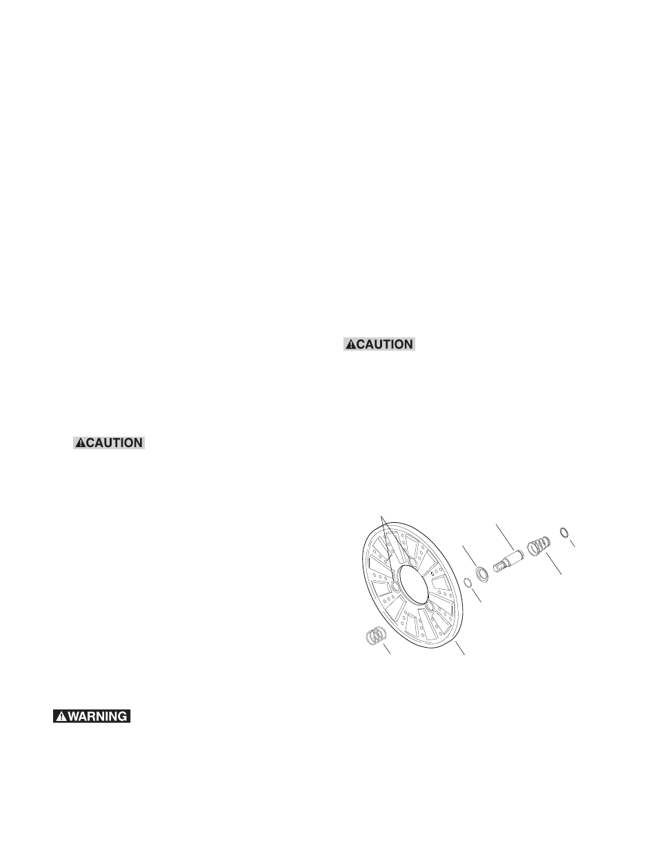
Step 3A: Place straight springs (white) over
each armature boss on the back side of
the armature.
Armature Boss
Straight Spring
(White)
Detent Spring
Retainer
Retainer
Ring
Detent
Spring
Drive Pin
Heavy
Spring
(Red)
Armature