Warner Electric ER 825 and 1225 Normal Duty User Manual
Page 11
11
Warner Electric • 800-825-9050
P-250 • 819-0122
prevent serious loss of torque by reducing the
coefficient of friction and swelling the friction
material. Small amounts of oil and grease
accidentally reaching the friction surfaces may be
removed by wiping with a rag dampened with a non
petroleum, non residue cleaning solution. In
performing this operation, do not drench the friction
material. If the friction material has been saturated
with oil or grease, no amount of cleaning will be
completely effective. Once such a unit has been
placed back in service, heat will cause the oil to be
boiled to the surface resulting in further torque loss.
This unit should then be replaced!
Fails to Release: If an Electrically Released Brake
does not release, the initial check should be to verify
the electrical connections (polarity) between the
brake coil and power supply. If the lead wires are
connected properly power supply positive (+)
terminal and brake coil (+) terminal, and power
supply negative (-) terminal and brake coil (-)
terminal, the next check is to see that the brake
release voltage adjustment is properly set in
accordance with installation instructions (see
Table of Contents).
If readjustment of the control output does not release
the brake and an AC input to the control is present,
a further check should be made to determine if the
control is faulty as follows:
Put machine in a safe condition
so that when voltage is applied to control and
switch closures are made the brake does not
rotate and machine does not run.
Connect a DC voltmeter across the brake magnet
terminals (do not disconnect the leads to the
terminals). Turn the torque adjustment on the control
fully counterclockwise, then slowly turn the
adjustment screw clockwise—the voltmeter should
indicate a voltage range from approximately 30 to 75
volts for the MCS-805 series and 0 to 90 volts using
other variable supplies.
To determine if there is current flow through the
magnet coil. Further checks may be made as
follows: a low-range (.1 to 1 amp) amp meter should
be connected in series with one wire to the magnet.
The Coil Data chart (page 9) lists the correct ratings
for the various sizes. These readings are with the
power on and the brake release adjustment turned
clockwise, until a voltmeter attached to the brake
magnet terminals reads 60 VDC. If no ampres are
read, an Ohm reading of the magnet coil should
be taken. Ohmmeter checks should be made with
the power off and circuit open (to be certain,
disconnect one lead wire to the coil). Refer to the
Coil Data chart (page 9) for the specifications of
the appropriate unit. A very high or infinite
resistance reading would indicate an open coil.
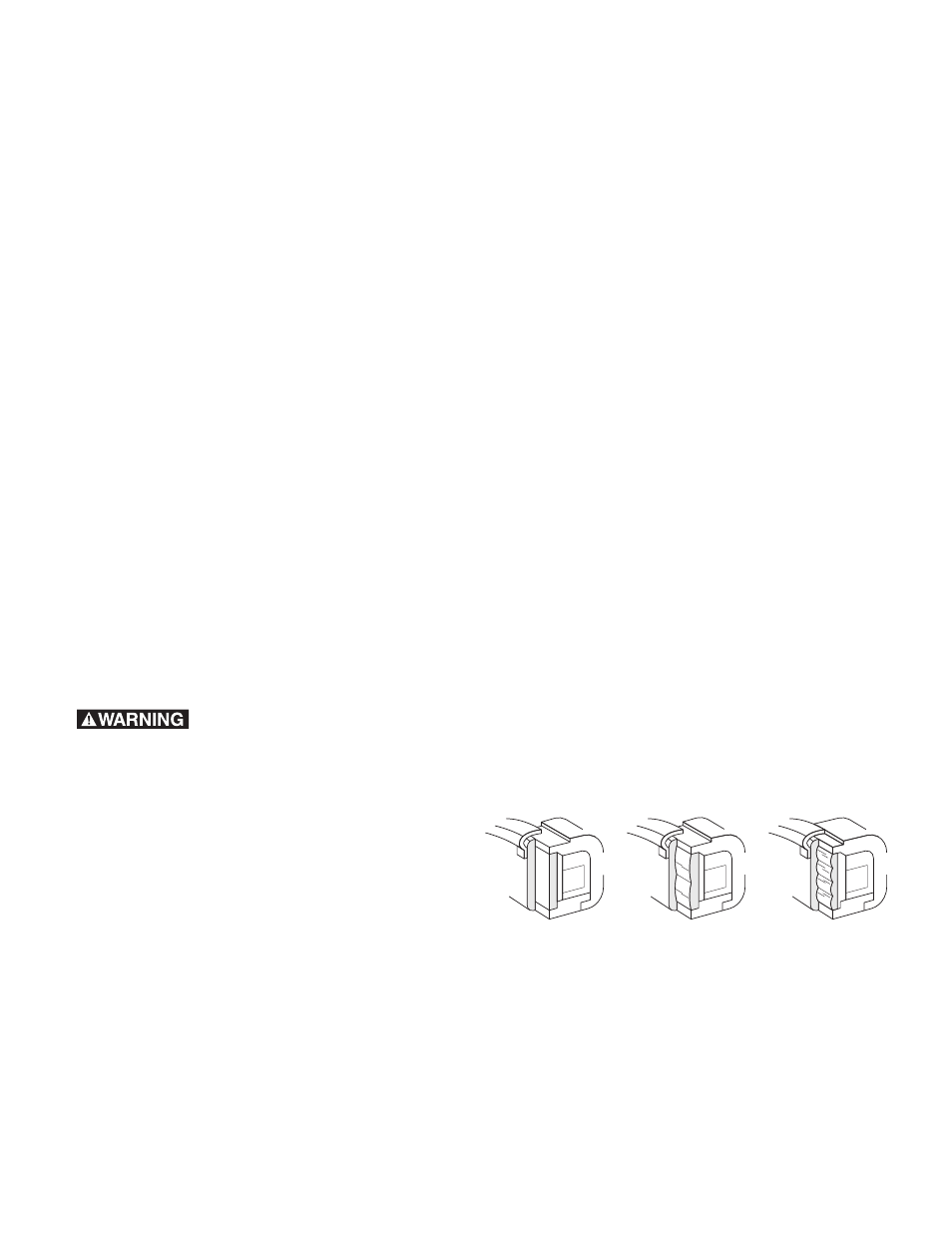
Wear Pattern: (Figure 4) As the brake is used
wear grooves will appear on the friction surfaces.
This is a normal condition, and does not impair
functioning of the unit.
Never machine the
friction surfaces to remove grooves or score
marks resulting from normal wear.
There are two main wear parts, magnet and
armature. When either is worn out, the
complete brake must be replaced.
Heat: Excessive heat and high-operating
temperatures are causes of rapid wear. Air should
be allowed to circulate around the unit as
efficiently as possible, especially if the application
requires fast, repetitive cycle operation.
If the above checks indicate that the proper
voltage and current is being supplied to the coil,
mechanical parts should be checked to assure
that they are in good operating condition and
properly installed. (See operating instruction under
Check No. 1).
Wear Pattern
NEW
BURNISHED
WORN
Figure 4