Reference information, Differential mode and common mode, Differential mode range and common mode range – Teledyne LeCroy AP033 User Manual
Page 54
AP033 Active Differential Probe
48
922260-00 Rev A
Reference Information
Differential Mode and Common Mode
Differential probes amplify the voltage difference that appears between the + and – inputs. This
voltage is referred to as the Differential Mode or Normal Mode voltage. The voltage component
that is referenced to earth ground, and is identical on both inputs, is rejected by the amplifier. This
voltage is referred to as the Common Mode voltage, because it is common to both inputs. The
common mode voltage can be expressed as:
Differential Mode Range and Common Mode Range
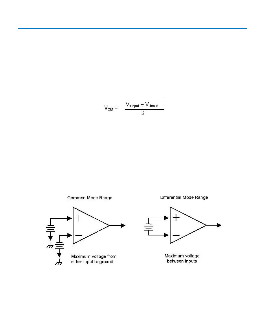
The Differential Mode Range is the maximum signal that can be applied between the + and –
inputs without overloading the probe amplifier, resulting in “clipping” or distortion of the
waveform measured by the oscilloscope.
The Common Mode Range is the maximum voltage with respect to earth ground that can be
applied to either input. Exceeding the common mode range can result in unpredictable results.
Because the Common Mode signal is normally rejected and is not displayed on the oscilloscope,
you need to be careful to avoid accidentally exceeding the common mode range.
Figure 11, Common Mode and Differential Mode Range