Designing test fixtures for the ap033 probe – Teledyne LeCroy AP033 User Manual
Page 22
AP033 Active Differential Probe
16
922260-00 Rev A
Upon successful completion of the Autobalance cycle, all four of the EFFECTIVE GAIN indicators will
be briefly illuminated. If an input signal is present during auto balancing and the routine fails, the
EFFECTIVE GAIN indicators will not illuminate. The probe will then revert to the offset values that
resulted from the last successful completion of the Autobalance cycle. In many situations, this will
be adequate to make routine measurements.
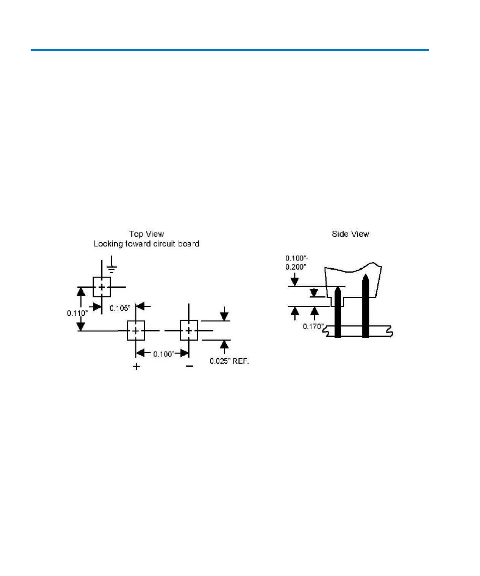
Designing Test Fixtures for the AP033 Probe
Often it is desirable to connect the probe directly to user fabricated test fixtures, such as those
used for semiconductor characterization. To facilitate use with custom test fixtures, the input
receptacles of the AP033 probe are compatible with commercially available 0.025 in. (0.635 mm)
square pins. The receptacles do not require a specific rotational alignment for the square pin. The
dimensions listed below can be used as a layout guide for a test fixture circuit board. The
recommended insertion depth of the pins is 0.100 in. (2.5 mm) to 0.200 in. (5.0 mm).
Figure 5, Layout dimensions for test fixtures