C. adjust fine dc balance (r304) – Teledyne LeCroy AP033 User Manual
Page 47
Operator’s Manual
922260-00 Rev A
41
C. Adjust Fine DC Balance (R304)
1. Remove the shorting plug from the Logic Board.
2. In the Channel 1 “COUPLING” menu, change the Probe Gain to X10.
3. Reinsert the shorting plug into the two holes near the end of the Logic Board. (Figure 6.)
4. Reenter Cal Mode by pushing any one of the four buttons that protrude through holes in
the Logic board.
5. Remove the BNC cable from the precision 50 Ω terminator attached to the DMM.
6. Short the output BNC connector by reconnecting the cable to the SHORT connector on the
AP033/AP034 Calibration Fixture. The SHORT connector is the only BNC connector on the
AP033/AP034 Calibration Fixture that does not have corresponding input pins for the probe
tip. It is located on the end of the board beyond the Common Mode Terminated connector.
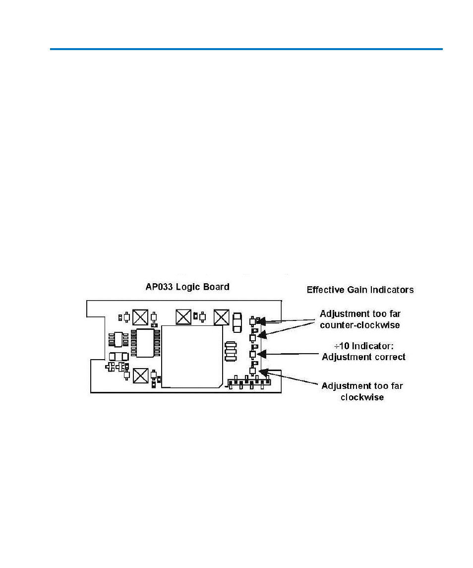
7. In Cal Mode, the EFFECTIVE GAIN indicators serve as an adjustment indicator. The
EFFECTIVE GAIN indicators are located on the Logic Board (See Figure 10.) It may be
necessary to hold the boards in your hands to see the indicators while making the
adjustment.
8. Adjust Fine DC Balance (R304) until the ±10 EFFECTIVE GAIN indicator lights.
Figure 10, ±10 Effective Gain Indicator
9. Disconnect the BNC cable from the short connector. Remove the shorting plug from the
logic board.