KB Electronics KBAC-48 User Manual
Page 9
9
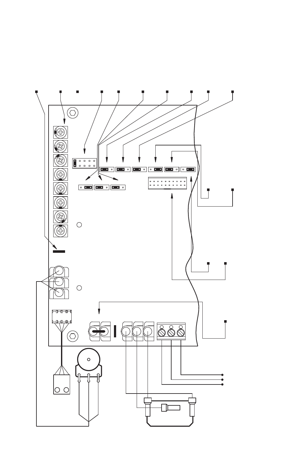
Output C
ontac
ts.
Run/F
ault Rela
y
Star
t/S
top S
wit
ch.
Main S
peed P
oten
tiomet
er.
Diagnostic LEDs
.
J4: 1X or up t
o 2X
J9: N
ormally O
pen or C
losed
J11: I
2
t O
verload selec
tion.
CON1: U
sed t
o c
onnec
t
optional ac
cessories t
o the driv
e.
Stop C
ontac
t selec
tion.
Tor
que selec
tion.
J10: C
onstan
t or
Variable
J7: Regener
ativ
e or
Output Rela
y O
per
ation selec
tion.
Injec
tion B
rak
ing selec
tion.
J8: "Run" or "F
ault"
J6: F
ixed or A
djustable B
oost selec
tion.
Rat
ed Mot
or RPM O
per
ation selec
tion.
Mot
or O
per
ation selec
tion.
J5: 60 H
z or 50 H
z
All jump
ers and tr
imp
ots ar
e sho
wn in fac
tor
y set p
ositions
.
J1: A
C Line Input
Voltage selec
tion
J2: Mot
or H
orsepo
wer selec
tio
n
3
.
(Models KBA
C-24D
, 27D only).
J3: A
utoma
tic R
ide
-Thr
oug
h
4
or Manual S
tar
t selec
tion.
Used with optional Run-S
top
-Jog S
wit
ch Kit
.
Adjustable T
rimpot
s
2
.
JOG T
erminal
.
See S
ection 6.6 on P
age 19.
See S
ection 6.7 on P
age 19.
See S
ection 6.4 on P
ages 18 - 19.
See S
ection 6.4 on P
ages 18 - 19.
See S
ection 6.5 on P
age 19.
See S
ection 6.1 on P
age 18.
See S
ection 6.2 on P
age 18.
See S
ection 6.3 on P
age 18.
See S
ection 13 on P
ages 23 – 26.
See
Table 2 on P
age 8.
See S
ection 5.5
See S
ection 5.9
on P
age 17.
on P
age 16.
Normally C
losed
Red
Normally O
pen
Rela
y C
ommon
See S
ection 5.4 on P
ages 15 - 16.
Black
Whit
e
See S
ection 6.10 on P
age 20.
See
Table 2 on P
age 8.
Used f
or optional
For
war
d-S
top
-Rev
erse
Swit
ch.
See S
ection 6.8 on P
age 19.
See S
ection 6.9 on P
age 20.
Whit
e (L
ow) (P1)
Violet (High) (P3)
Orange (
Wiper) (P2)
See S
ection 12 on P
age 23.
STA
TUS
PO
WER
STOP
NC
NO
COM
FWD
COM
RUN
REV
COM
CON2
JOG
P1
P3
P2
ACCEL
MIN
MAX
JOG
CL
DECEL
BOOST
TB2
M
A
J3
2X
J4
50Hz
J5
60Hz
1X
J8
J9
NC
NO
F
J11
J10
CT
2
1
VT
CON1
FIX
J6
RG
R
INJ
J7
ADJ
A
J2
E
C D
B
COMP
Figur
e 2 – C
ontr
ol L
ay
out
1
Not
es: 1.
La
yout of Mo
del KB
AC
-24D v
ar
ies slightly
. 2.
On Mo
del KB
AC
-24D
, the JOG and C
OMP T
rimp
ots ar
e lo
ca
ted v
er
tic
ally
, along the r
ight edge of the PC b
oar
d (b
elo
w the mounting sc
rew).
3.
On Mo
del KB
AC
-24D
, Jump
er J2 is lab
eled “1”
, “3/4”
, “1/2”
, “1/4”
,
“1/8” (fac
tor
y set t
o the “1” p
osition). O
n Mo
del KB
AC
-27D
, Jump
er J2 is lab
eled “2”
, “11⁄2”
, “1”
, “3/4”
, “1/2” (fac
tor
y set t
o the “11⁄2” p
osition). O
n Mo
dels KB
AC
-29, 29 (1P
), 45, 48, J
ump
er J2 is lab
eled “
A”, “B”
, “
C”, “D
”, “E
” (fac
tor
y set ac
cor
ding t
o T
able 4 on page 10.
4.
On Mo
del KB
AC
-24D
, Jump
er J3 is lab
eled “
AUT
O” and “
MAN”
.