0 – 5 volts dc, 0 – 10 volts dc – KB Electronics KBAC-48 User Manual
Page 16
16
To operate the drive from a
remote potentiometer (5 kΩ),
remove the white, orange,
and violet potentiometer
leads from Terminals “P1”,
“P2”, and “P3”. The wires may
be taped and left inside the
drive. The potentiometer
assembly may be removed
if a watertight seal is used to
cover the hole in the front
cover. Wire the Main Speed
Potentiometer to Terminals
“P1” (low side), “P2” (wiper),
and “P3” (high side). See
Figure 9 on page 15.
WARNING! Do not earth ground any
Main Speed Potentiometer terminals.
Application Note – If it is required that the Remote
Main Speed Potentiometer be isolated from the AC
line, install the SIAC Signal Isolator (Part No. 9600).
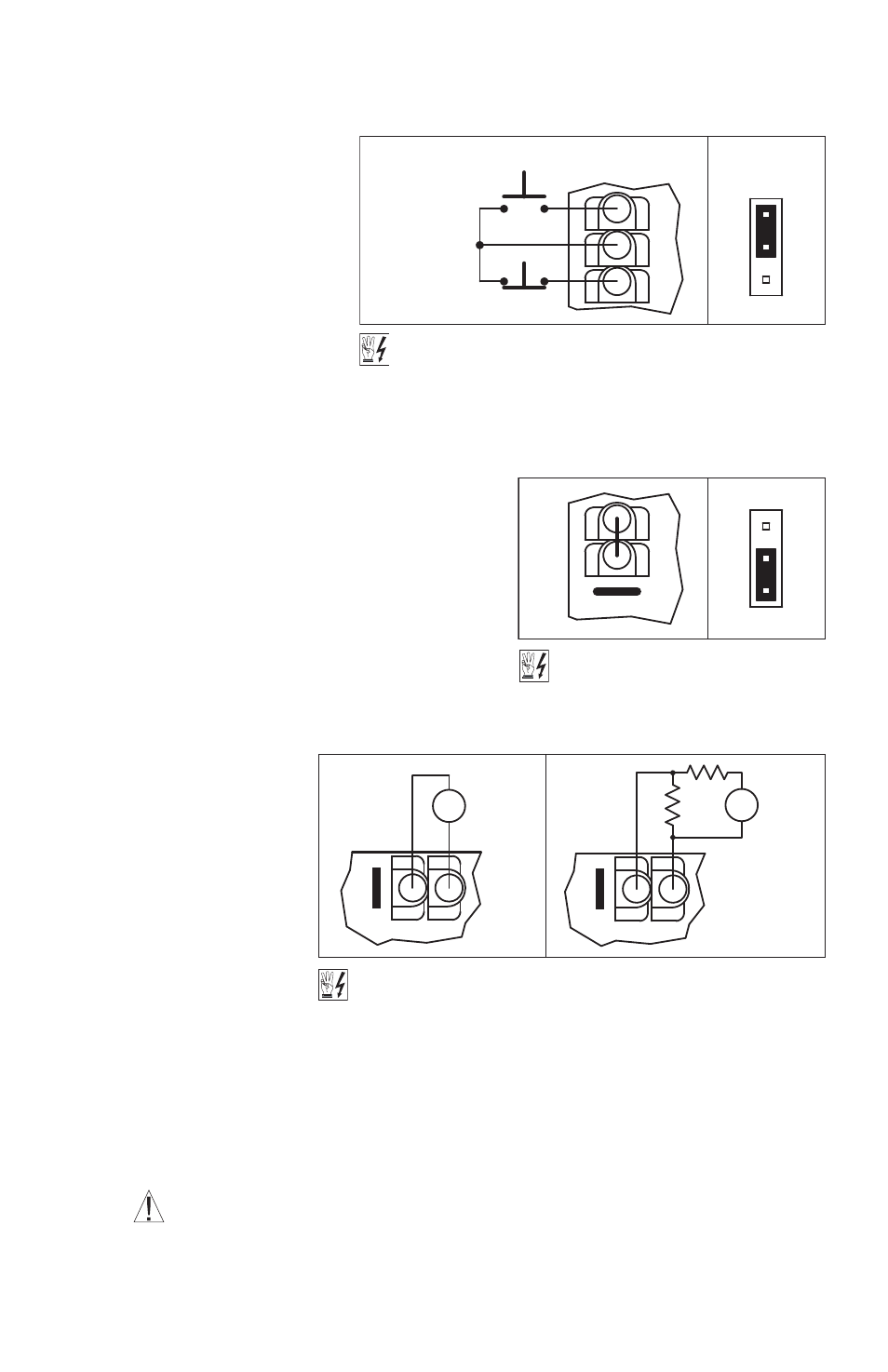
5.5 Remote Start/Stop Switch Connection –
The drive is supplied with a prewired Start/Stop
Switch mounted on the front cover to electronically
start and stop the drive.
To operate the drive from a remote Start/Stop
Switch (type ON-OFF-ON, SPDT), remove the white,
black, and red wires from Terminals “RUN”, “COM”,
and “STOP”. The wires may be taped and left inside
the drive. The switch assembly may be removed if a
liquidtight seal is used
to cover the hole in
the front cover. After
applying power to the
drive, momentarily set
the Start/Stop Switch
to the “START” position.
For Start/Stop Switch
with normally closed
stop contact, set
Jumper J9 to the “NC”
position. See Figure 10
on page 15 and Figure
11. Also see Section 6.8
on page 19.
5.6 Automatic Restart – Automatic restart requires the elimination of the Start/Stop Switch. Remove
the white, black, and red wires from Terminals “RUN”, “COM”, and “STOP”. The wires may be taped
and left inside the drive. The switch assembly may be removed if a liquidtight seal is used to cover
the hole in the front cover.
To eliminate the Start/Stop function, hardwire Terminals ”RUN” and “COM” with the jumper that is
provided. Be sure Jumper J9 is set to the “NO” position. See Figure 12.
WARNING! Using a jumper to eliminate the Start/Stop function will cause the motor to
run at the Main Speed Potentiometer setting when the AC line is applied.
HIGH VOLTAGE! See Warning on Page 14.
NO
J9
NC
CO
M
(Push to Stop)
Normally Closed
Momentary Contact
STOP
STOP
Normally Open
Momentary Contact
(Push to Start)
RUN
START
Figure 11 – Remote Start/Stop Switch Connection
with Normally Closed Stop Contact
(J9 Installed in “NC” Position)
NO
J9
NC
CO
M
STOP
RUN
HIGH VOLTAGE!
See Warning on Page 14.
Figure 12 – Start/Stop Function Eliminated
(Terminals Hardwired) (Jumper Installed)
(J9 Installed in “NO” Position)
HIGH VOLTAGE! See Warning on Page 14.
0 – 5
Volts DC
P2
P3
P1
V
-
+
0 – 10
Volts DC
P2
P3
P1
10k
V
10k
-
+
Figure 13 – Voltage Following Connections (Isolated)