Figure 30 – minimum speed trimpot range, Figure 31 – maximum speed trimpot range, Figure 32 – acceleration trimpot range – KB Electronics KBAC-48 User Manual
Page 23
23
a fuse (Littelfuse 312/314, Buss ABC, or equivalent) or a circuit breaker in series with each ungrounded
conductor. Do not fuse motor leads. For the recommended fuse size, see Table 4 on page 10.
Wire the drive in accordance with the National Electrical Code requirements and other local codes that
may apply to the application.
12 DIAGNOSTIC LEDs
The drive contains two diagnostic LEDs mounted on the enclosure cover to display the drive’s
operational status.
12.1 Power On LED (PWR) – The “PWR” LED will illuminate green when the AC line is applied to the drive.
WARNING! Do not depend on the PWR LED as a guaranteed power off condition.
Be sure the main power switch or circuit breaker is in the “OFF” position before
servicing this drive.
12.2 Status LED (ST) – The “ST” LED is a tricolor LED which provides indication of a fault or abnormal
condition. The information provided can be used to diagnose an installation problem such as incor-
rect input voltage, overload condition, and drive output miswiring. It also provides a signal which
informs the user that all drive and microcontroller operating parameters are normal.
Table 7, summarizes the “ST” LED functions.
Table 7 – Drive Operating Condition and Status LED Indicator
Drive Operating Condition
Flash Rate
1
and LED Color
Normal Operation
Slow Flash Green
Overload (120% – 160% Full Load)
Steady Red
2
I
2
t (Drive Timed Out)
Quick Flash Red
2
Short Circuit
Slow Flash Red
Undervoltage
Quick Flash Red / Yellow
3
Overvoltage
Slow Flash Red / Yellow
3
Stop
Steady Yellow
Stand-By
4
Slow Flash Yellow
Input Phase Loss
5
Rapid Flash Yellow
Notes: 1. Slow Flash = 1 second on and 1 second off. Quick Flash = 0.25 second on and 0.25 second off. 2. When the Overload is removed, before
the I
2
t times out and trips the drive, the “ST” LED will flash green. 3. When the Undervoltage or Overvoltage condition is corrected, the “ST” LED
will flash Red / Yellow / Green. 4. Only if the Forward-Stop-Reverse Switch is installed. 5. Model KBAC-29, with three-Phase AC line input, and
Models KBAC-45, 48. Rapid Flash = 4 mSec on and 6 mSec off.
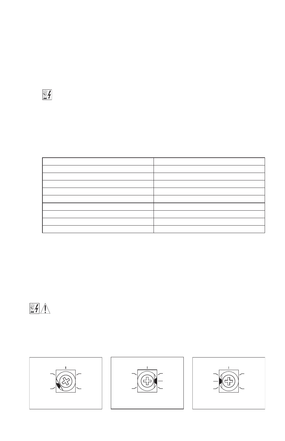
13 TRIMPOT ADJUSTMENTS
The drive contains trimpots which are factory set for most applications. See Figure 2 on page 9 for the
location of the trimpots and their approximate factory calibrated positions. Some applications may
require readjustment of the trimpots in order to tailor the drive for a specific requirement. The trimpots
may be readjusted as described below.
WARNING! If possible, do not adjust trimpots with the main power applied. If adjust-
ments are made with the main power applied, an insulated adjustment tool must be
used and safety glasses must be worn. High voltage exists in this drive. Fire and/or electrocution
can result if caution is not exercised. The Safety Warning on page 5 must be read and understood
before proceeding.
(Shown Factory Set to 0% Frequency Setting)
0
MIN
40
15
35
30
Figure 30 – Minimum Speed
Trimpot Range
(Shown Factory Set to 100% Frequency Setting)
70
MAX
110
75
90
100
80
Figure 31 – Maximum Speed
Trimpot Range
0.3
(Shown Factory Set to 1.5 Seconds)
ACCEL
20
3
1.5
17
10
Figure 32 – Acceleration
Trimpot Range