KB Electronics KBAC-48 User Manual
Page 15
15
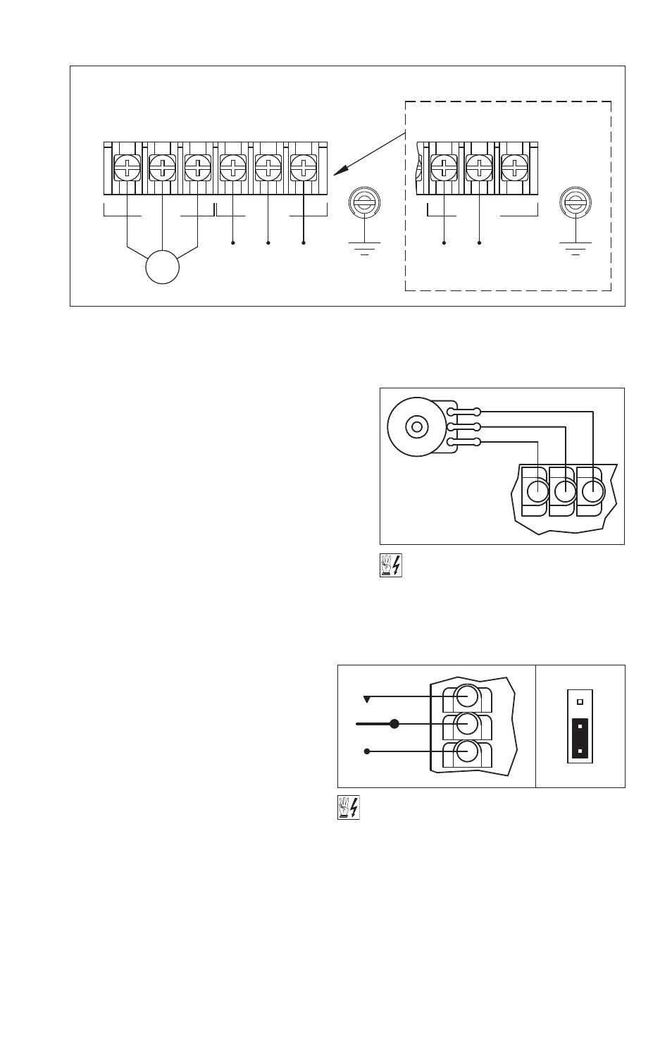
Models KBAC-24D, 27D: Designed to accept
single-phase AC line input only (Terminals “L1”,
“L2”). Rated for 208/230 Volt AC line input with
Jumper J1 set to the “230V” position (factory
setting). Rated for 115 Volt AC line input with
Jumper J1 set to the “115V” position. See Figure 7
on page 14.
Model KBAC-29: Designed to accept single-phase
(Terminals “L1”, “L2”) or 3-phase (Terminals “L1”,
“L2”, “L3”) AC line input. Rated for 208/230 Volt AC
line input only. See Figure 8. (See note above.)
Model KBAC-29(1P): Designed to accept
single-phase AC line input (Terminals “L1”, “L2”).
Rated for 208/230 Volt AC line input only. See
Figure 7 on page 14.
Models KBAC-45, 48: Designed to accept
3-phase AC line input only (Terminals “L1”,
“L2”, “L3”). Rated for 400/460 Volt AC line
input only. See Figure 8.
5.2 Ground Connection – Connect the
Ground Wire (Earth) to the Green Ground
Screw. The Ground Screw is located next to
Terminal Block TB1. See Figure 7 on page
14 and Figure 8.
5.3 Motor Connection – Wire the motor to
Terminal Block TB1 Terminals “U”, “V”, “W”.
See Figure 7 on page 14 and Figure 8.
Motor cable length should not exceed
100 ft (30 m) – special reactors may be
required – consult our Sales Department.
Be sure Jumper J2 is set to the corresponding motor horsepower rating, as described in Section 6.2
on page 18.
5.4 Remote Main Speed Potentiometer Connection – The drive is supplied with a prewired Main
Speed Potentiometer mounted on the front cover.
*Note: model KBAC-29 is rated 2 HP maximum with single-phase AC line input and 3 HP maximum with 3-phase AC line input.
to Terminals "L1", "L2", as shown below.
Model KBAC-29 Only
Wire the single-phase AC line input
208/230 Volt
AC Line Input
Single-Phase, 50/60 Hz
Ground (Earth)
L3
L2
L1
AC LINE
Ground (Earth)
3-Phase, 50/60 Hz
208/230, 400/460 Volt
Motor
AC Line Input
W
U
V
MOTOR
TB1
L1
L3
L2
AC LINE
Figure 8 – Models KBAC-29*, 45, 48 AC Line Input, Motor, and Ground Connections
Figure 9 – Remote Main Speed
Potentiometer Connection
Main Speed
Potentiometer
Orange (Wiper)
Violet (High)
White (Low)
P1
P2
P3
HIGH VOLTAGE!
See Warning on Page 14.
Figure 10 – Remote Start/Stop Switch Connection
with Normally Open Stop Contact
(J9 Installed in “NO” Position)
CO
M
Black
STOP
STOP
Red
START
RUN
White
NO
J9
NC
HIGH VOLTAGE! See Warning on Page 14.