IAI America TU-MA96-P User Manual
Page 9
8
INTELLIGENT ACTUATOR
[3] LED
indicators
This unit has LED indicators that show the DO power-input status for each connector.
If external power is not input or a fuse on the board is blown, the applicable LED will turn off.
All fuses are resettable (meaning that the fuse will reconnect automatically once an overcurrent
condition is removed). One fuse is provided for each group of eight DOs.
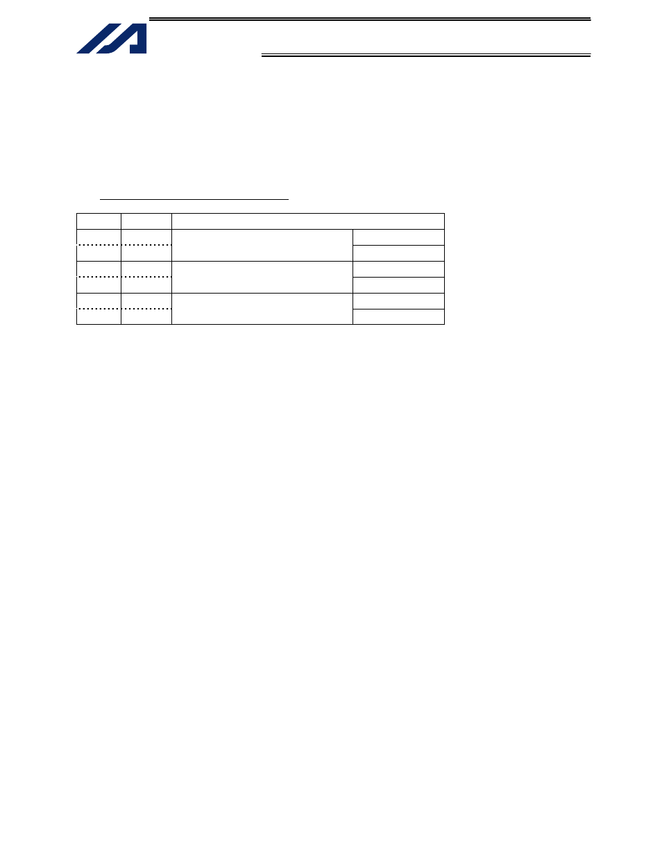
Table 3-4 LED Indicator Specifications
Symbol
Color
Applicable external power input
LED1 Green
OUT00
∼ 07
LED2 Green
CN2 external power-input indicator
OUT08
∼ 15
LED3 Green
OUT16
∼ 23
LED4 Green
CN3 external power-input indicator
OUT24
∼ 31
LED5 Green
OUT32
∼ 39
LED6 Green
CN4 external power-input indicator
OUT40
∼ 47
[4] External
power-supply
open detection switch (SW1)
This unit is capable of outputting a detection signal indicating absence of external DO power supply (24
VDC) to the X-SEL controller.
To use this function, the dedicated switch (SW1) must be set to the ON position.
In the power-supply open detection mode, IN47 becomes a dedicated input for detection signal.
The applicable X-SEL controller parameter must also be set to specify error detection input for the
terminal block unit.
I/O parameter No. 23: Specification of overcurrent/power-supply error detection input for multi-point
DIO external terminal block
Example 1) To detect power-supply open failure only for the unit connected to the multi-point I/O
board in expansion slot I/O1 (I/O2), set I/O parameter No. 23 to “20.”
Example 2) To detect power-supply open failure for both units connected to the multi-point I/O
boards in expansion slots I/O1 (I/O2) and I/O2 (I/O3), set I/O parameter No. 23 to “220.”
If you want to use IN47 as a normal general-purpose input instead of an open-failure detection signal,
be sure to set the switch to the OFF position.