Configuration, 1 system configuration – IAI America TU-MA96-P User Manual
Page 3
2
INTELLIGENT ACTUATOR
2. Configuration
2.1 System
Configuration
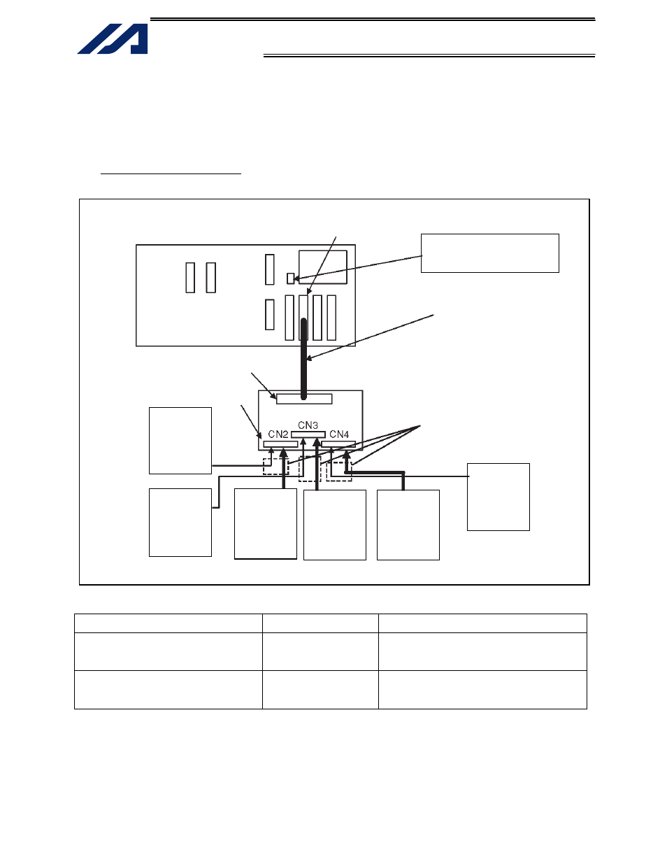
Fig. 2-1 Connection Example
Model Name
Connection
Half-pitch I/O flat cable
(w/ connectors on both ends)
CB-X-PIOH020-H6
For connection between the controller’s
multi-point DIO board and the DIO
terminal block unit.
I/O flat cables
(w/ connector on one end)
CB-RCBC-PIO020
For connection between the DIO terminal
block unit and peripheral equipment.
X-SEL general-purpose controller (type K)
Connect a 24-VDC power supply
to the IO24V power-input
connector on the panel board.
Input common
24 VDC
(IN32
∼ 39)
(IN40
∼ 47)
Output power
supply
24 VDC
(OUT32
∼ 39)
(OUT40
∼ 47)
Output power
supply
24 VDC
(OUT16
∼ 23)
(OUT24
∼ 31)
Output power
supply
24 VDC
(OUT00
∼ 07)
(OUT08
∼ 15)
Input common
24 VDC
(IN16
∼ 23)
(IN24
∼ 31)
Input common
24 VDC
(IN00
∼ 07)
(IN08
∼ 15)
I/O flat cables
Half-pitch I/O flat cable
40-pin MIL connector
DIO terminal block unit
Half-pitch connector
Multi-point I/O board