IAI America IA-IO-3205-PN User Manual
Page 13
12
INTELLIGENT ACTUATOR
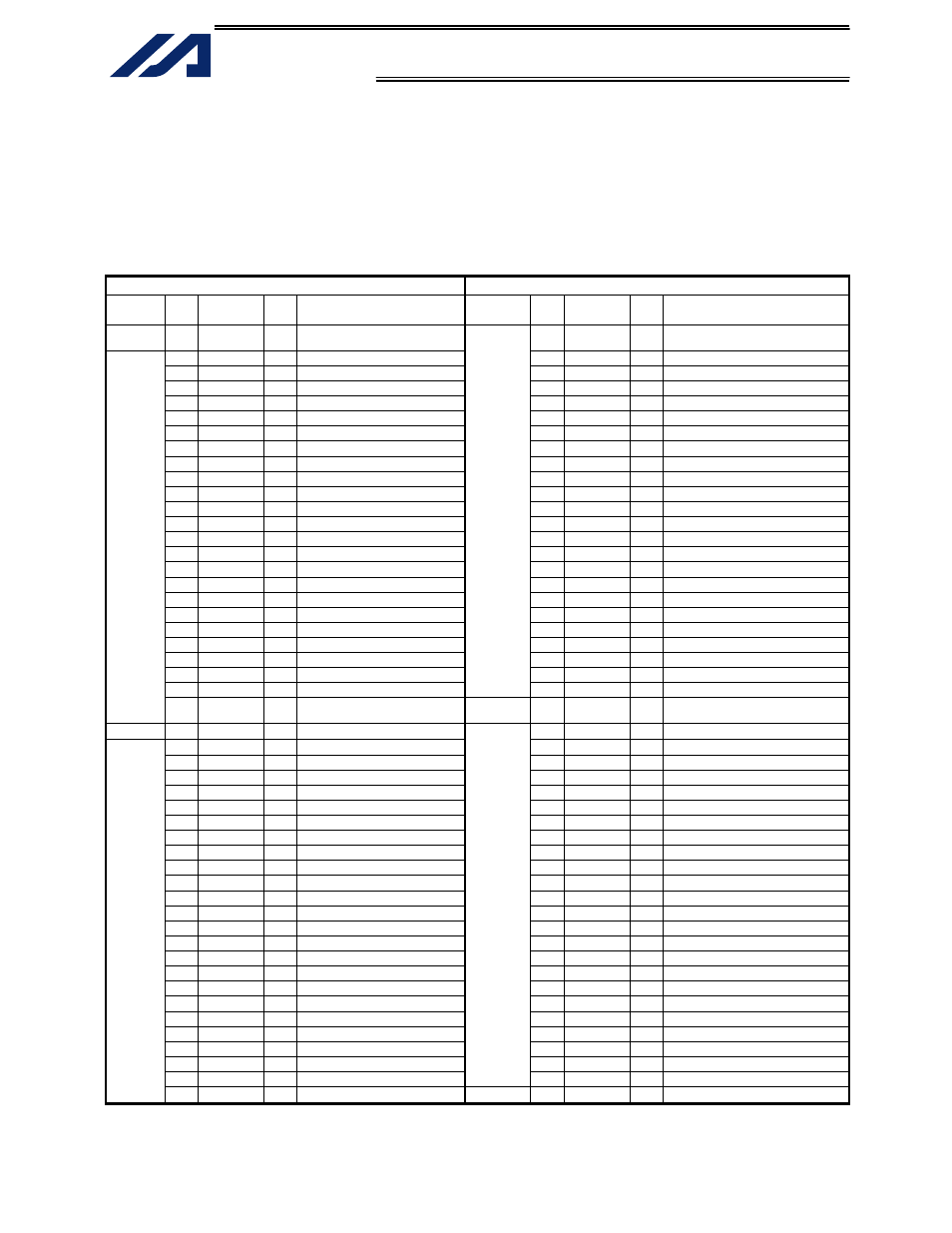
Example of interface list 3 (cable w/ connector on one end)
Multi-point DIO board for K-Type controller, second board
The interface list below assumes that the second multi-point DIO board is installed in expansion slot 2
(I/O3).
(When one multi-point DIO board is added to the condition in the previous example)
I/O parameter No. 1 = “1” (Automatic assignment)
Note) The IO24V power supply on the controller’s panel board is connected to pin Nos. 26 and 100.
Pin No. 26: 24 VDC Pin No. 100: 0 V (power supply for pin Nos. 27 to 50/76 to 99)
Cable 1
Cable 2
Category
Pin
No.
Color
Port
No.
Function Category
Pin
No.
Color
Port
No.
Function
−
1 Brown-1
−
External power supply (24 VDC)
for pin Nos. 2 to 25/51 to 74
51 Brown-1 364 User
Output
2
Red-1
080 User Input
52 Red-1
365 User Output
3
Orange-1 081 User Input
53 Orange-1 366 User Output
4
Yellow-1
082 User Input
54 Yellow-1
367 User Output
5
Green-1
083 User Input
55 Green-1
368 User Output
6
Blue-1
084 User Input
56 Blue-1
369 User Output
7
Purple-1
085 User Input
57 Purple-1
370 User Output
8
Gray-1
086 User Input
58 Gray-1
371 User Output
9
White-1
087 User Input
59 White-1
372 User Output
10 Black-1
088 User Input
60 Black-1
373 User Output
11 Brown-2
089 User Input
61 Brown-2
374 User Output
12 Red-2
090 User Input
62 Red-2
375 User Output
13 Orange-2 091 User Input
63 Orange-2 376 User Output
14 Yellow-2
092 User Input
64 Yellow-2
377 User Output
15 Green-2
093 User Input
65 Green-2
378 User Output
16 Blue-2
094 User Input
66 Blue-2
379 User Output
17 Purple-2
095 User Input
67 Purple-2
380 User Output
18 Gray-2
096 User Input
68 Gray-2
381 User Output
19 White-2
097 User Input
69 White-2
382 User Output
20 Black-2
098 User Input
70 Black-2
383 User Output
21 Brown-3
099 User Input
71 Brown-3
384 User Output
22 Red-3
100 User Input
72 Red-3
385 User Output
23 Orange-3 101 User Input
73 Orange-3 386 User Output
24 Yellow-3 102 User
Input
Output
74 Yellow-3 387 User
Output
Input
25 Green-3 103 User
Input
−
75 Green-3
−
External power supply (0 VDC) for
pin Nos. 2 to 25/51 to 74
−
26 Blue-3
− Note) (24 VDC)
76 Blue-3
388 User Output
27 Purple-3
104 User Input
77 Purple-3
389 User Output
28 Gray-3
105 User Input
78 Gray-3
390 User Output
29 White-3
106 User Input
79 White-3
391 User Output
30 Black-3
107 User Input
80 Black-3
392 User Output
31 Brown-4
108 User Input
81 Brown-4
393 User Output
32 Red-4
109 User Input
82 Red-4
394 User Output
33 Orange-4 110 User Input
83 Orange-4 395 User Output
34 Yellow-4
111 User Input
84 Yellow-4
396 User Output
35 Green-4
112 User Input
85 Green-4
397 User Output
36 Blue-4
113 User Input
86 Blue-4
398 User Output
37 Purple-4
114 User Input
87 Purple-4
399 User Output
38 Gray-4
115 User Input
88 Gray-4
400 User Output
39 White-4
116 User Input
89 White-4
401 User Output
40 Black-4
117 User Input
90 Black-4
402 User Output
41 Brown-5
118 User Input
91 Brown-5
403 User Output
42 Red-5
119 User Input
92 Red-5
404 User Output
43 Orange-5 120 User Input
93 Orange-5 405 User Output
44 Yellow-5
121 User Input
94 Yellow-5
406 User Output
45 Green-5
122 User Input
95 Green-5
407 User Output
46 Blue-5
123 User Input
96 Blue-5
408 User Output
47 Purple-5
124 User Input
97 Purple-5
409 User Output
48 Gray-5
125 User Input
98 Gray-5
410 User Output
49 White-5 126 User
Input
Output
99 White-5 411 User
Output
Input
50 Black-5 127 User
Input
−
100 Black-5
− Note) (0 VDC)