IAI America IA-IO-3205-PN User Manual
Page 12
11
INTELLIGENT ACTUATOR
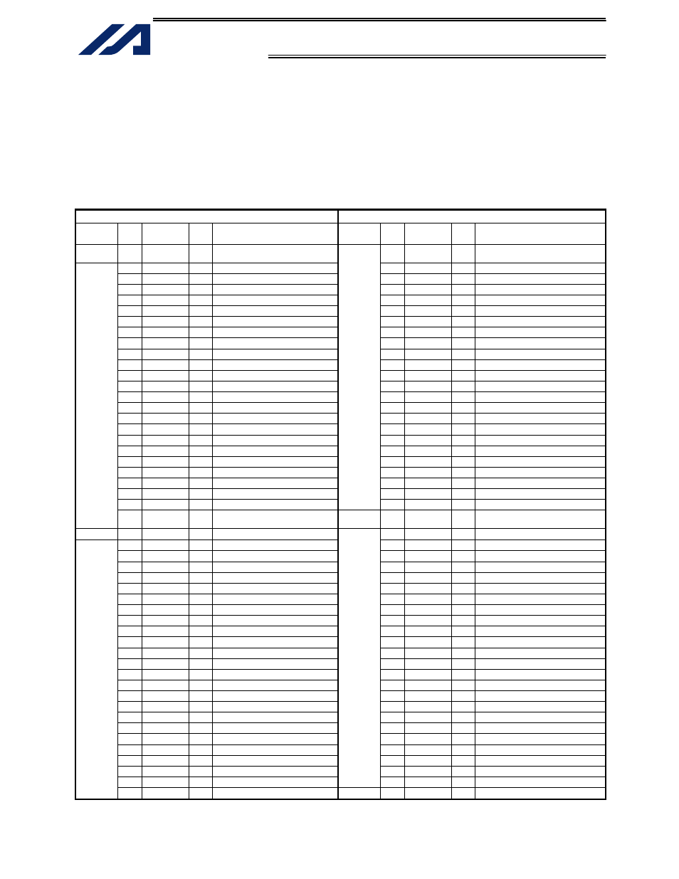
Example of interface list 2 (cable w/ connector on one end)
Multi-point DIO board for K-Type controller, first board
The interface can be installed in expansion slot 1 (I/O2) or any subsequent expansion slot of the type-K
controller.
The interface list below assumes that the first multi-point DIO board is installed in expansion slot 1
(I/O2).
I/O parameter No. 1 = “1” (Automatic assignment)
Note) The IO24V power supply on the controller’s panel board is connected to pin Nos. 26 and 100.
Pin No. 26: 24 VDC Pin No. 100: 0 V (power supply for pin Nos. 27 to 50/76 to 99)
Cable 1
Cable 2
Category
Pin
No.
Color
Port
No.
Function Category
Pin
No.
Color
Port
No.
Function
−
1 Brown-1
−
External power supply (24 VDC)
for pin Nos. 2 to 25/51 to 74
51 Brown-1 316 User
Output
2
Red-1 032
User
Input
52
Red-1 317 User
Output
3
Orange-1 033 User Input
53 Orange-1 318 User Output
4 Yellow-1 034
User
Input
54 Yellow-1 319 User
Output
5 Green-1 035
User
Input
55
Green-1 320 User
Output
6
Blue-1 036
User
Input
56
Blue-1 321 User
Output
7 Purple-1 037
User
Input
57 Purple-1 322 User
Output
8
Gray-1 038
User
Input
58
Gray-1 323 User
Output
9
White-1 039
User
Input
59
White-1 324 User
Output
10 Black-1
040 User Input
60 Black-1
325 User Output
11
Brown-2 041
User
Input
61
Brown-2 326 User
Output
12
Red-2 042
User
Input
62
Red-2 327 User
Output
13 Orange-2 043 User Input
63 Orange-2 328 User Output
14 Yellow-2 044
User
Input
64 Yellow-2 329 User
Output
15
Green-2 045
User
Input
65
Green-2 330 User
Output
16
Blue-2 046
User
Input
66
Blue-2 331 User
Output
17 Purple-2 047
User
Input
67 Purple-2 332 User
Output
18
Gray-2 048
User
Input
68
Gray-2 333 User
Output
19
White-2 049
User
Input
69
White-2 334 User
Output
20 Black-2
050 User Input
70 Black-2
335 User Output
21
Brown-3 051
User
Input
71
Brown-3 336 User
Output
22
Red-3 052
User
Input
72
Red-3 337 User
Output
23 Orange-3 053 User Input
73 Orange-3 338 User Output
24 Yellow-3 054 User
Input
Output
74 Yellow-3 339 User
Output
Input
25 Green-3 055 User
Input
−
75 Green-3
−
External power supply (0 VDC) for
pin Nos. 2 to 25/51 to 74
−
26 Blue-3
− Note) (24 VDC)
76 Blue-3
340 User Output
27 Purple-3 056
User
Input
77 Purple-3 341 User
Output
28
Gray-3 057
User
Input
78
Gray-3 342 User
Output
29
White-3 058
User
Input
79
White-3 343 User
Output
30 Black-3
059 User Input
80 Black-3
344 User Output
31
Brown-4 060
User
Input
81
Brown-4 345 User
Output
32
Red-4 061
User
Input
82
Red-4 346 User
Output
33 Orange-4 062 User Input
83 Orange-4 347 User Output
34 Yellow-4 063
User
Input
84 Yellow-4 348 User
Output
35
Green-4 064
User
Input
85
Green-4 349 User
Output
36
Blue-4 065
User
Input
86
Blue-4 350 User
Output
37 Purple-4 066
User
Input
87 Purple-4 351 User
Output
38
Gray-4 067
User
Input
88
Gray-4 352 User
Output
39
White-4 068
User
Input
89
White-4 353 User
Output
40 Black-4
069 User Input
90 Black-4
354 User Output
41
Brown-5 070
User
Input
91
Brown-5 355 User
Output
42
Red-5 071
User
Input
92
Red-5 356 User
Output
43 Orange-5 072 User Input
93 Orange-5 357 User Output
44 Yellow-5 073
User
Input
94 Yellow-5 358 User
Output
45
Green-5 074
User
Input
95
Green-5 359 User
Output
46
Blue-5 075
User
Input
96
Blue-5 360 User
Output
47 Purple-5 076
User
Input
97 Purple-5 361 User
Output
48
Gray-5 077
User
Input
98
Gray-5 362 User
Output
49 White-5 078 User
Input
Output
99 White-5 363 User
Output
Input
50 Black-5 079 User
Input
−
100 Black-5
− Note) (0 VDC)