Examples of interface, J-type controller – IAI America IA-IO-3205-PN User Manual
Page 11
10
INTELLIGENT ACTUATOR
6. Examples of Interface
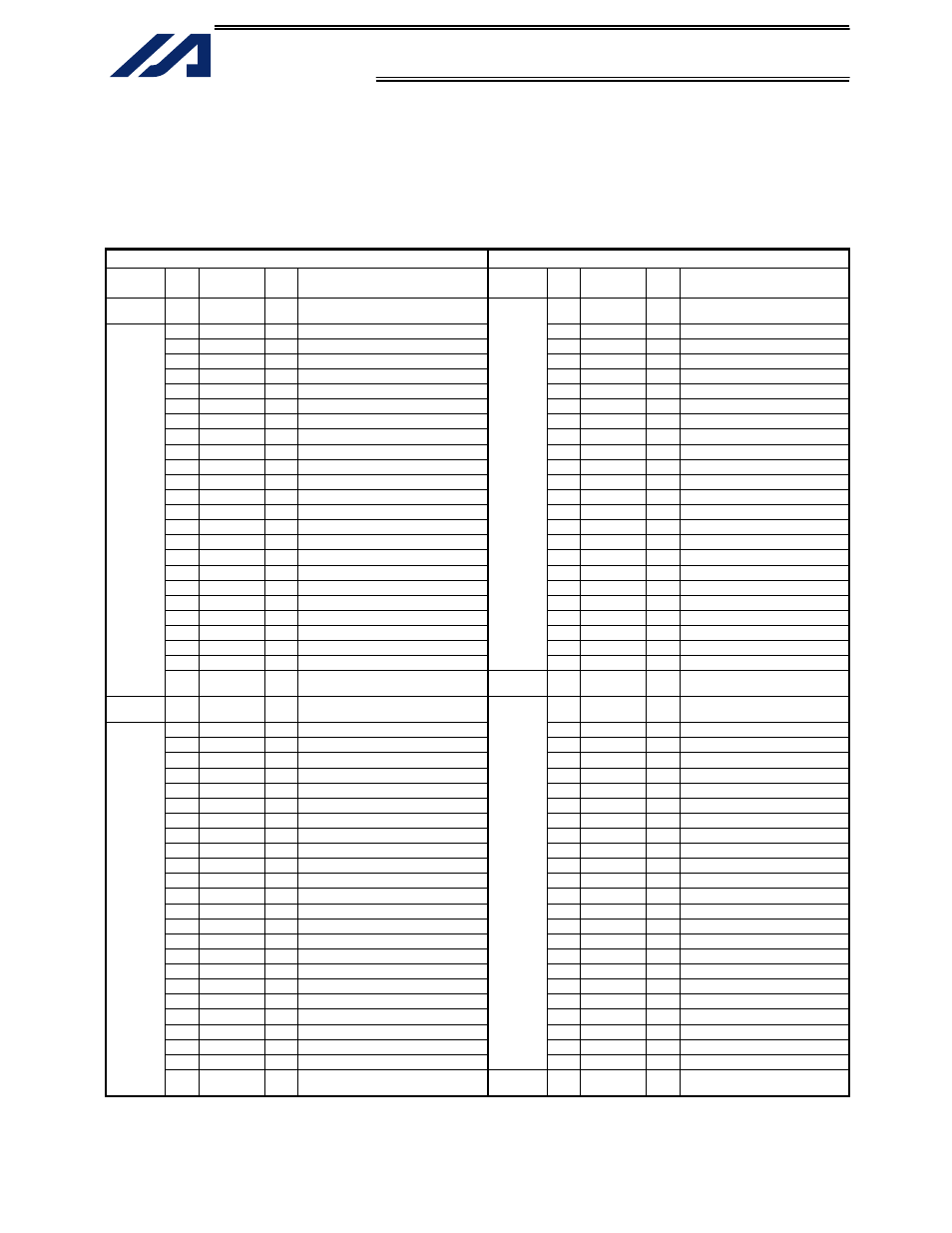
Example of interface list 1 (cable w/ connector on one end)
J-Type controller
The interface can be installed in standard slot 1 (I/O1) of the type-J controller.
The Function column indicates the factory settings.
Cable 1
Cable 2
Category
Pin
No.
Color
Port
No.
Function Category
Pin
No.
Color
Port
No.
Function
−
1 Brown-1
−
External power supply (24 VDC) for
pin Nos. 2 to 25/51 to 74
51 Brown-1 300 Alarm
output
2
Red-1 000
Program
start
52
Red-1 301
Ready
output
3 Orange-1 001 User
Input
53 Orange-1 302 Emergency-stop
output
4 Yellow-1 002 User
Input
54 Yellow-1 303 User
Output
5 Green-1 003
User
Input
55
Green-1 304
User
Output
6
Blue-1 004
User
Input
56
Blue-1 305
User
Output
7 Purple-1 005
User
Input
57 Purple-1 306
User
Output
8
Gray-1 006
User
Input
58
Gray-1 307
User
Output
9 White-1 007
Program specification (PRG No. 1)
59 White-1 308 User
Output
10 Black-1 008
Program specification (PRG No. 2)
60 Black-1 309 User
Output
11 Brown-2 009
Program specification (PRG No. 4)
61 Brown-2 310 User
Output
12 Red-2
010
Program specification (PRG No. 8)
62 Red-2
311 User
Output
13 Orange-2 011
Program specification (PRG No. 10)
63 Orange-2 312 User
Output
14 Yellow-2 012
Program specification (PRG No. 20)
64 Yellow-2 313 User
Output
15 Green-2 013
Program specification (PRG No. 40)
65 Green-2 314 User
Output
16
Blue-2 014
User
Input
66
Blue-2 315
User
Output
17 Purple-2 015
User
Input
67 Purple-2 316
User
Output
18
Gray-2 016
User
Input
68
Gray-2 317
User
Output
19
White-2 017
User
Input
69
White-2 318
User
Output
20
Black-2 018
User
Input
70
Black-2 319
User
Output
21
Brown-3 019
User
Input
71
Brown-3 320
User
Output
22
Red-3 020
User
Input
72
Red-3 321
User
Output
23 Orange-3 021 User
Input
73 Orange-3 322 User
Output
24 Yellow-3 022 User
Input
Output
74 Yellow-3 323 User
Output
Input
25 Green-3 023 User
Input
−
75 Green-3
−
External power supply (0 VDC)
for pin Nos. 2 to 25/51 to 74
−
26 Blue-3
−
External power supply (24 VDC) for
pin Nos. 27 to 50/76 to 99
76 Blue-3
324 User
Output
27 Purple-3 024
User
Input
77 Purple-3 325
User
Output
28
Gray-3 025
User
Input
78
Gray-3 326
User
Output
29
White-3 026
User
Input
79
White-3 327
User
Output
30
Black-3 027
User
Input
80
Black-3 328
User
Output
31
Brown-4 028
User
Input
81
Brown-4 329
User
Output
32
Red-4 029
User
Input
82
Red-4 330
User
Output
33 Orange-4 030 User
Input
83 Orange-4 331 User
Output
34 Yellow-4 031 User
Input
84 Yellow-4 332 User
Output
35
Green-4 032
User
Input
85
Green-4 333
User
Output
36
Blue-4 033
User
Input
86
Blue-4 334
User
Output
37 Purple-4 034
User
Input
87 Purple-4 335
User
Output
38
Gray-4 035
User
Input
88
Gray-4 336
User
Output
39
White-4 036
User
Input
89
White-4 337
User
Output
40
Black-4 037
User
Input
90
Black-4 338
User
Output
41
Brown-5 038
User
Input
91
Brown-5 339
User
Output
42
Red-5 039
User
Input
92
Red-5 340
User
Output
43 Orange-5 040 User
Input
93 Orange-5 341 User
Output
44 Yellow-5 041 User
Input
94 Yellow-5 342 User
Output
45
Green-5 042
User
Input
95
Green-5 343
User
Output
46
Blue-5 043
User
Input
96
Blue-5 344
User
Output
47 Purple-5 044
User
Input
97 Purple-5 345
User
Output
48
Gray-5 045
User
Input
98
Gray-5 346
User
Output
49 White-5 046 User
Input
Output
99 White-5 347 User
Output
Input
50 Black-5 047 User
Input
−
100 Black-5
−
External power supply (0 VDC)
for pin Nos. 27 to 50/76 to 99