O figure 3-29, O figure 3-30 – Harrington Hoists and Cranes GT Trolley User Manual
Page 34
6)
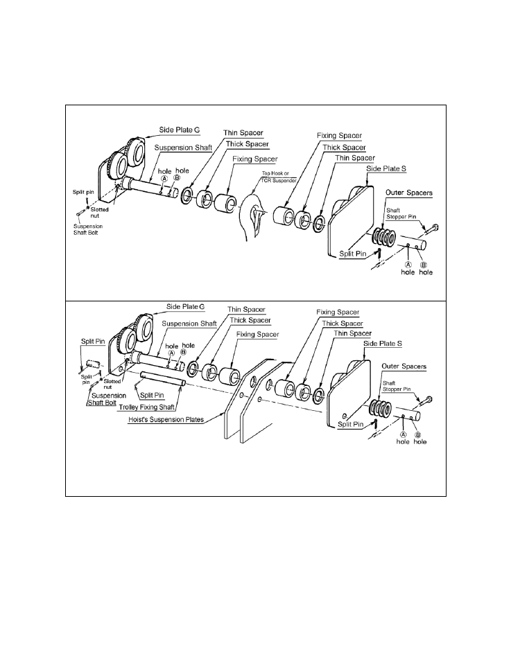
For the (N)ER/(N)ER2 hoists – Insert the Trolley Fixing Shaft through Side Plate G, Suspension plates and Side
Plate S. Refer to Figure 3-30. Secure it to side Plate G with two split pins. Securely bend both branches of the
Split Pin after insertion.
Figure 3-29 Assembling the Trolley - 8 Through 10 Ton Capacity, CB or TCR
Note:
Trolley Fixing Shaft is shown in front of Suspension Shaft for clarity. Actual location is behind the
Suspension Shaft.
Figure 3-30 Assembling the Trolley - 8 Through 10 Ton Capacity, (N)ER/(N)ER2
Refer to Figure 3-31 for 15-20 Ton coupled with Manual CB hoist
Refer to Figure 3-32 for 15-20 Ton coupled with (N)ER/(N)ER2 hoist
1)
Remove the Shaft Stopper Pin, Side Plate S, and Spacers from the Suspension Shaft. For beam flanges that are
wider than the standard range, different suspension shaft and/or spacer arrangements are provided. Refer to
Table 3-1.
34