Harrington Hoists and Cranes GT Trolley User Manual
Page 32
3.4
Trolley Assembly
Refer to Figure 3-27 for ½ through 3 Ton.
Refer to Figure 3-28 for 5 Ton.
1) Remove the Shaft Stopper Pin, Side Plate SN, and Spacers from the Suspension Shaft. For beam flanges that are
wider than the standard range, different suspension shaft and/or spacer arrangements are provided. Refer to Table
3-1.
2) Insert the Suspension Shaft to Side Plate G or S and attach it with the Shaft Stopper Pin and Split Pin (cotter pin).
Refer to Figure 3-33 to ensure that the correct Suspension Shaft holes are used. Securely bend both branches of
the Split Pin after insertion.
3) Referring to Figure 3-35, Table 3-1 and Table 3-2 install the inner adjusting Spacers and Suspender on the
Suspension Shaft. Use all of the Spacers provided with the trolley. If the beam width is not listed in the Table, use
the next size smaller and make adjustments in accordance with Section 3.3.8.
4) Place Side Plate SN into the Suspension Shaft.
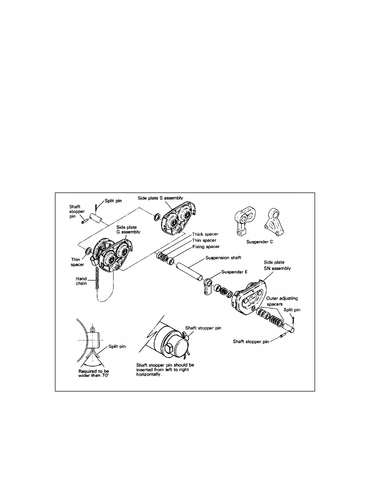
5) Install the outer adjusting Spacers on the Suspension Shaft outside of Side Plate SN. Insert the Shaft Stopper Pin
into Suspension Shaft. Temporarily install the split pin in the Shaft Stopper Pin and bend the split pin slightly to hold
it in place. The split pin should be fully bent after checking and attaining the proper beam flange adjustment
Figure 3-27 Assembling the Trolley – Up Through 3 Ton Capacity
32