Harrington Hoists and Cranes (N)ER Hoist - ((N)ER2) User Manual
Page 33
33
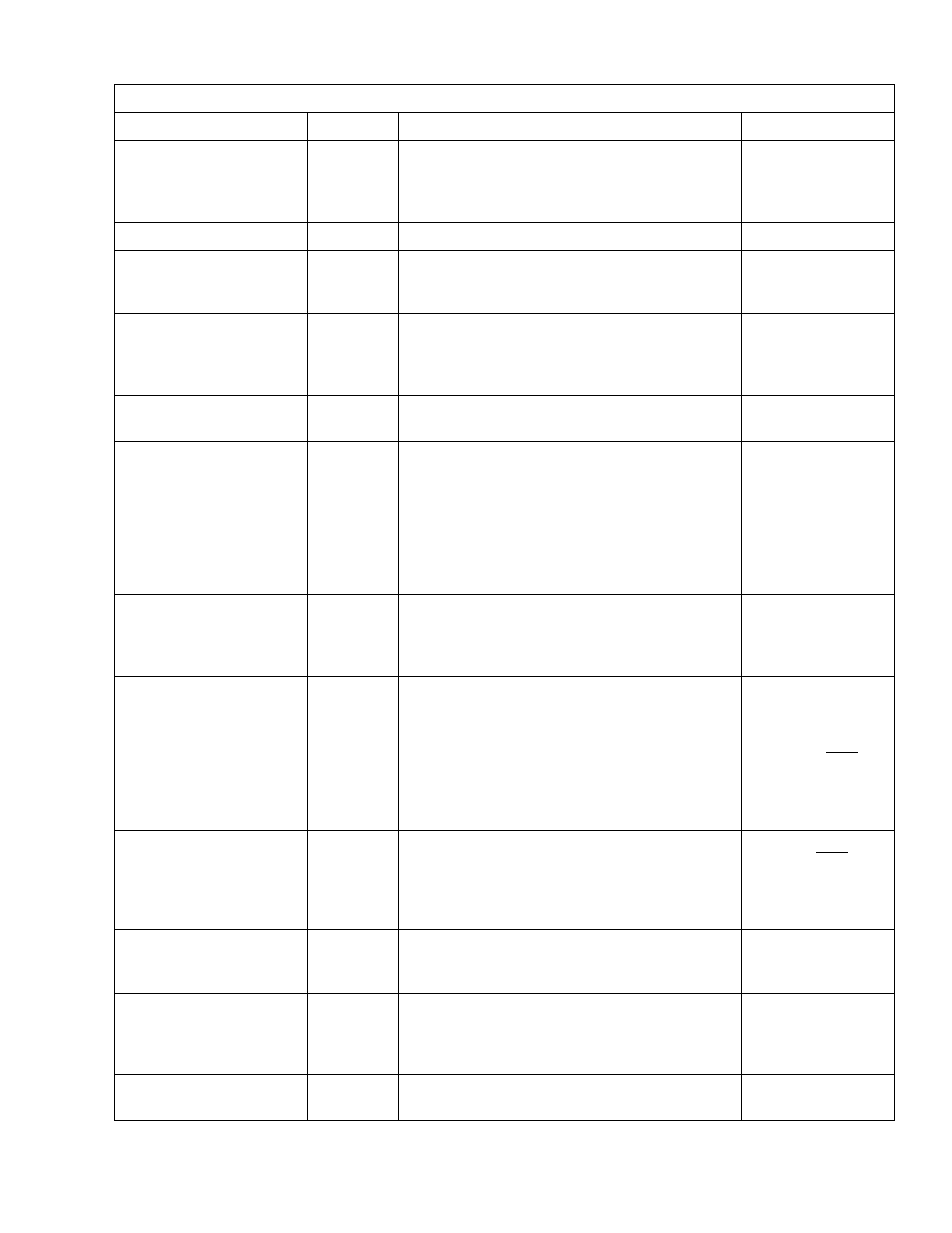
Table 5-3 Hoist Inspection Methods and Criteria
Item
Method
Criteria
Action
Load Chain
– Connection
Yoke Chain Pin (Double
Reeved Hoists Only)
Measure
The Connection Yoke Chain Pin should not have
and appare
nt deformation. The “d” dimension
should not be less than the discard value listed in
Table 5-6.
Replace.
Cushion Rubber
Visual
Should be free of significant deformation.
Replace.
Chain Springs
Visual
Chain springs should not be deformed or
compressed. Refer to Table 5-9 for Chain Spring
dimensions.
Replace.
Chain Guide
Visual
Chain Guide should be free of significant wear.
Chain Guide surfaces should be free of
deformation by nicks, gouges, and abrasion.
Refer to Figure 5-3.
Replace.
Chain Container (optional)
Visual
Container should not be damaged. Brackets
should not be deformed or missing.
Replace.
Housing and Mechanical
Components
Visual,
Auditory,
Vibration,
Function
Hoist components including load blocks,
suspension housing, chain attachments, clevises,
yokes, suspension bolts, shafts, gears, bearings,
pins and rollers should be free of cracks,
distortion, significant wear and corrosion.
Evidence of same can be detected visually or via
detection of unusual sounds or vibration during
operation.
Replace.
Bolts, Nuts and Rivets
Visual,
Check with
Proper
Tool
Bolts, nuts and rivets should not be loose.
Tighten or replace
as required.
Electromagnetic Brake
Assembly
Measure,
Visual
The electromagnetic motor brake gap is directly
related to brake disk wear. As the disk wears, the
brake gap will increase. The brake gap/wear
dimension should not be more than discard value
listed in Table 5-7. Bolts and screws should not
be loose.
Tighten bolts and
screws as required
or replace Brake
Assembly. Note:
DO NOT attempt to
adjust or dis-
assemble the Brake
Assembly.
Hub Joint
Visual
Hub Joint should have no apparent deformation
and abrasion. Must be fully seated. Refer to
Figure 5-4.
Replace. Note:
Electromagnetic
Brake Assembly
may also need to be
replaced.
V Ring
Visual
The V Ring should not be worn or show any
abnormality. It should be well lubricated. Refer to
Figure 5-5 and Section 6.1.7.
Clean/lubricate or
replace as required.
Contactor Contacts
Visual
Contacts should be free of significant pitting or
deterioration. On hoists equipped with
Count/Hour Meter check the contactor cycles
–
refer to Section 6.1.
Replace.
VFD (Dual Speed only)
Visual,
Function
There should be no fault codes (Reference
Section 3.6.)
Replace as needed.