Harrington Hoists and Cranes (N)ER Hoist - ((N)ER2) User Manual
Page 14
14
3.2
Chain
3.2.1
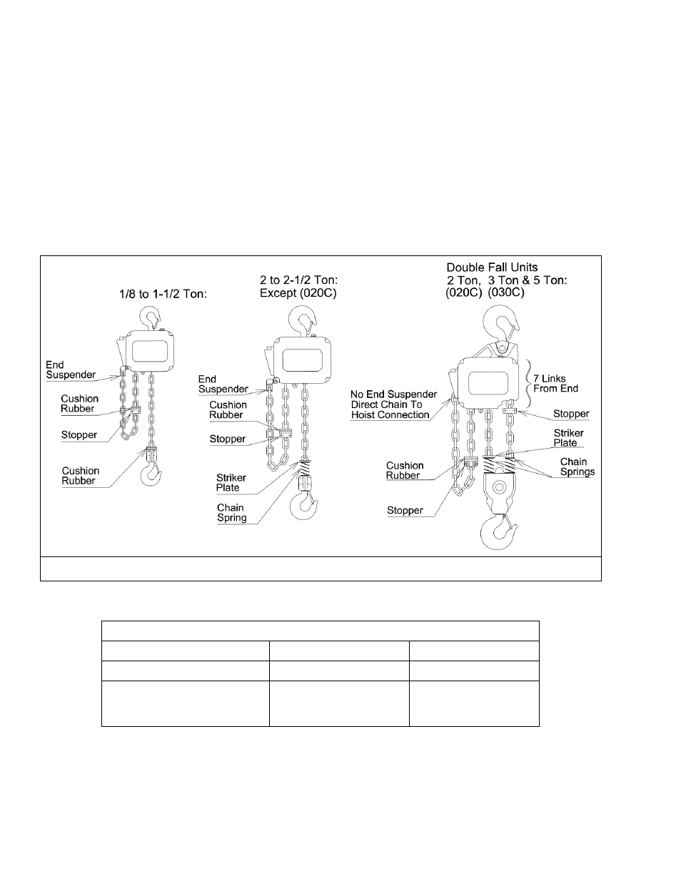
The quantity and location of the chain components including cushion rubbers, chain springs, and striker
plates depend on the hoist model, capacity, and limits switches. Never operate the hoist with incorrect,
missing, or damaged chain components. Refer to the hoist's nameplate, Table 3-1, as well as Figures
3-2, 3-3. Ensure that all chain components are in the correct location and properly installed.
3.2.2
When the hoist is used without a chain container, the free end of the chain is attached to the hoist body
as shown in Figure 3-4. Connect the no load end of the chain to Chain Guide A with the End
Suspender provided. For 5 ton hoist, connect the no load end of the chain directly to Chain Guide A if
Chain Guide A is notched to accept the chain. Make sure the chain remains free of twists and the
chain Stopper is installed on the correct link. Refer to Table 3-1 for proper placement of Stopper.
Figure 3-2 Chain Component Arrangement for Single Fall and Double Fall Hoists.
Table 3-1 Chain Stopper Placement
Capacity Code
Without Chain Container
With Chain Container
001H & 003S
21
st
link from the free end
3
rd
link from the free end
003H, 005L, 005S, 010L, 010S,
015S, 020C, 020L, 020S, 025S,
030L, 030C, 050L
15
th
link from the free end
3
rd
link from the free end
*Tightening torque for the Stopper Bolt: 10 N-m (7 lb-ft)