Harrington Hoists and Cranes LB Lever Hoist - (L5) User Manual
Page 42
42
6.4.8
Hoist Lever and Body
1) Attach the Lever assembled in Section 6.4.2 to the previously assembled Brake. Fit (29) Brake
Cover assembly and (10) Frame A assembly by screwing (33) Female Thread of the Lever
assembly clockwise to the thread of (16) Pinion until it makes a clicking sound. Make sure the flat
part of the Brake Cover aligns with the flat on Frame A.
2) Fasten (29) Brake Cover assembly firmly to the Stay Bolts with (14) Acorn Nuts and (15) Spring
Lock Washer.
3)
To eliminate a clearance in the Brake section, perform the following
procedures before moving onto the next step.
A) Set the Selector Lever to
„N‟ position.
B) Turn (33) Female Thread clockwise to tighten the Brake lightly with (52) Load chain at the
hook side held by hand firmly without (19) Load Sheave
‟s rotation.
C)
The hoist will make “clicking” sounds if the chain is not being held sufficiently. The clearance
will be reduced while the hoist is “clicking”. After tightening, make sure that the Female Thread
will not rotate counterclockwise on the (16) Pinion.
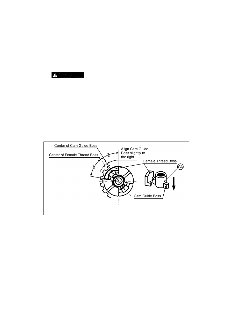
4) To attach (44) Cam Guide to (16) Pinion, aligning the boss of the Guide slightly to the right of the
middle of (33) Female Thread
‟s boss as shown in Figure 6-12.
5) Apply (G3) grease lightly to the side of (44) Cam Guide.
Figure 6-12 Cam Guide