Harrington Hoists and Cranes LB Lever Hoist - (L5) User Manual
Page 36
36
6.4.2
Lever
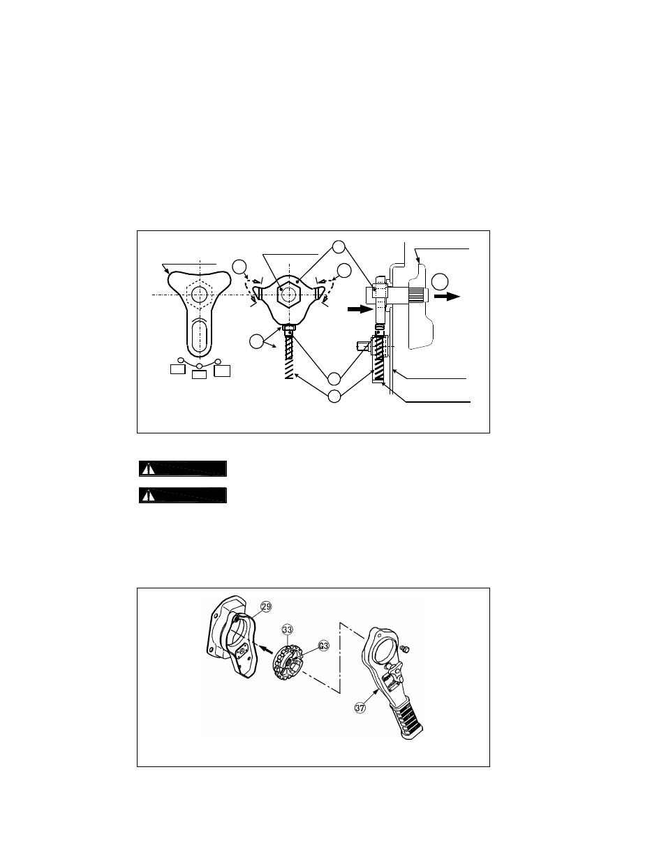
Refer to Figure 6-1, proceed as follows:
1) Set the Selector Lever on the (37) lever assembly to the „N‟ position.
2) With the Selector Lever pulled in the „a‟ direction, as shown in the left picture, insert the hex part of
the Selector Lever into (34) Select pawl.
3) Apply (G1) grease lightly to the pawl of (34) Select Pawl and to the top of (35) Spring Shaft as
shown in Figure 6-1.
4) Insert (35) Spring Shaft into (36) Select-Pawl spring and attach them into the Spring Holder.
Select lever
Spring holder
Lever Upper side
N
DN
UP
Select lever
a
G1
{
34
36
35
G1
G1
Hex part
Pull fully
Hold firmly
Figure 6-1 Internal Lever Assembly
Refer to Figure 6-2, proceed as follows.
1)
Do not apply oil to the friction side of the Female Thread.
2)
Clean the friction side of the Female Thread.
3) Apply (G3) grease lightly to the thread of (33) Female Thread.
4) Place (33) Female Thread, friction side first into the (29) Brake Cover assembly.
5) Install (37) Lever assembly onto (29) Brake Cover Assembly and secure with (42) Hex Cap Screw
and (30) Flange Nuts.
Figure 6-2 Lever Assembly