Harrington Hoists and Cranes LB Lever Hoist - (L5) User Manual
Page 38
38
6.4.4
Load Sheave and Chain Assembly
1) For LB008 to LB030 hoists attach (4) Bottom Hook set to (52) Load chain with (8) Slotted Nut and
(7) Split Pin.
2) For LB060 and LB090 hoists apply (G1) grease the bearing surface of the (17) Shaft Assembly
and (16) (17) Idle Sheave. Install the shaft and sheave into the (13) Bottom or (4) Top Yoke
assembly and secure the yokes with (14) bolts and (15) Lever Nuts.
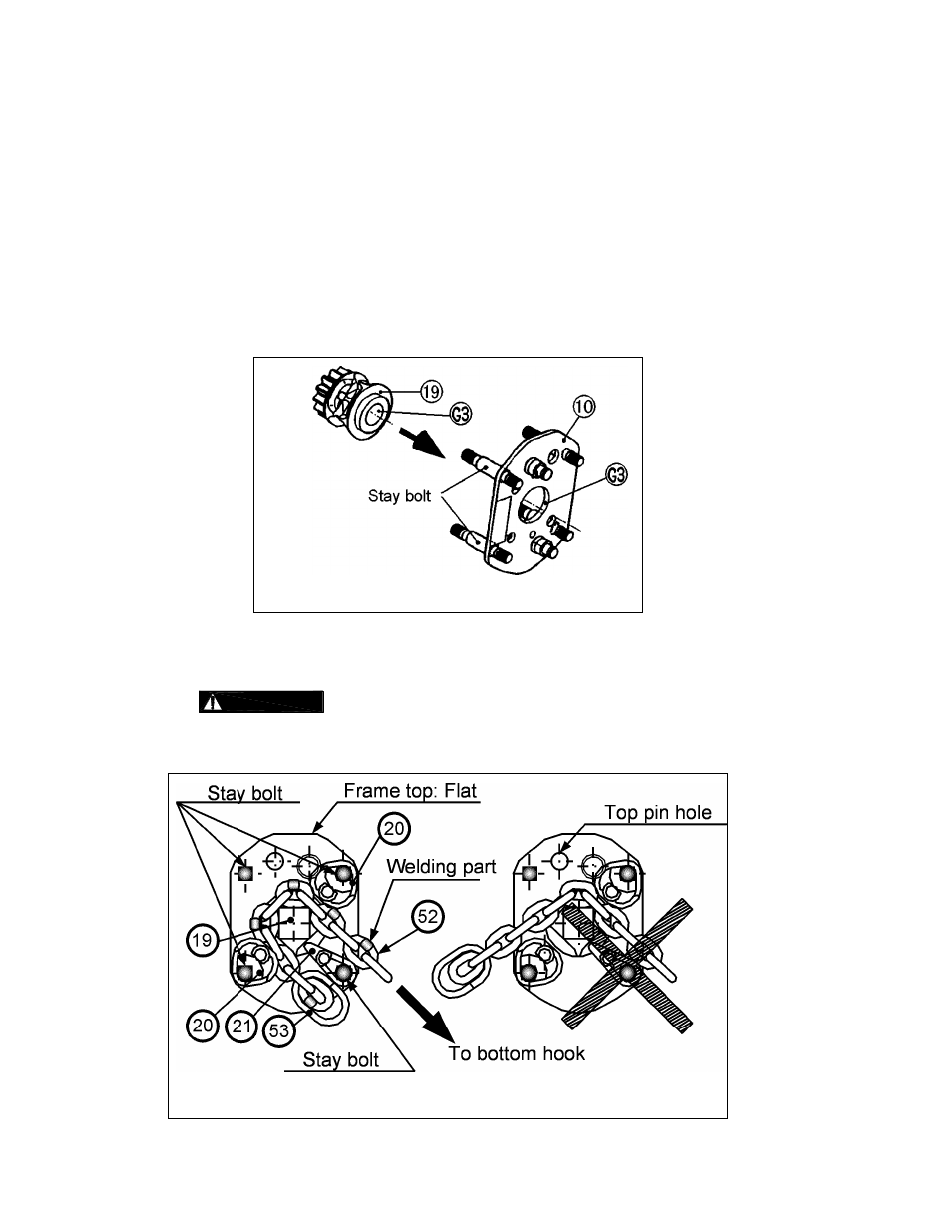
3) Apply (G3) grease to the inner parts of the bearing hole of (10) Frame A Assembly and (19) Load
Sheave as shown in Figure 6-5.
4) Attach (19) Load Sheave to (10) Frame A Assembly on Stay Bolt side with the gear or spline
oriented as shown in Figure 6-5.
Figure 6-5 Load Sheave Attachment to Frame A Assy
5) Place the (52) Load chain on (19) Load Sheave and install (20) Chain Guides and (21) Stripper.
Refer to Figure 6-6.
6)
Orient the load chain with the (53) Chain stopper link parallel to the frame and
welds to the outside of the Load Sheave.
Figure 6-6 Load Chain Reeving Direction