Gilderfluke&Co old Smart Brick Manual User Manual
Page 68
column) of the 40 pin IDS connector. The first and last ten pins are bussed to all of the cards in the card
cage.
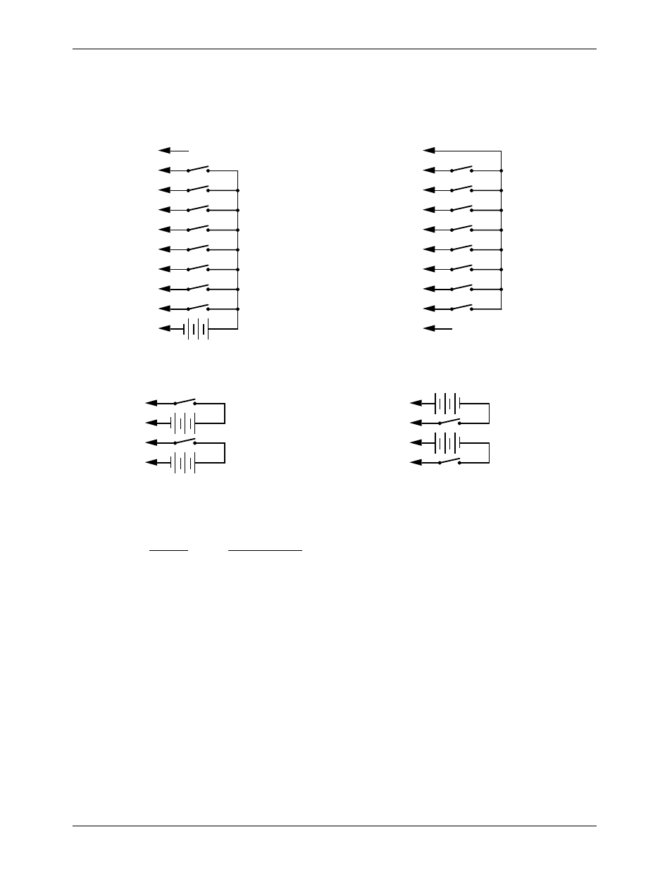
The 1/4 J6 Input is optically isolated. It can be set to run from an external power source (default con-
figuration) or the same power as the Rack Smart Brick Brain. This is selected by moving the two jumpers
on JP-2 as shown on the board. Both jumpers to the left set the 1/4 J6 to internal power. Both jumpers to
the right set the 1/4 J6 to external power.
SUPPLY (not used)
+
(Brown) PIN #1
(red) PIN #2
(orange) PIN #3
(yellow) PIN #4
(green) PIN #5
(blue) PIN #6
(violet) PIN #7
(grey) PIN #8
(white) PIN #9
(black) PIN #10
GROUND (not used)
DATA BIT 7
DATA BIT 6
DATA BIT 5
DATA BIT 4
DATA BIT 3
DATA BIT 2
DATA BIT 1
DATA BIT 0
+ 5 to 24 VDC SUPPLY
GROUND
DATA BIT 7
DATA BIT 6
DATA BIT 5
DATA BIT 4
DATA BIT 3
DATA BIT 2
DATA BIT 1
DATA BIT 0
Internal Power
External Power
(Brown) PIN #1
(red) PIN #2
(orange) PIN #3
(yellow) PIN #4
(green) PIN #5
(blue) PIN #6
(violet) PIN #7
(grey) PIN #8
(white) PIN #9
(black) PIN #10
The Connections to the J-8 input are as follows. These inputs are optoisolated. You must provide a
voltage to them:
+
+ GREEN #18
- BLUE #19
+ BLUE #20
+ 5 to 24 VDC SUPPLY
+
- GREEN #17
+ 5 to 24 VDC SUPPLY
+ GREEN #18
- BLUE #19
+ BLUE #20
+
+ 5 to 24 VDC SUPPLY
+
- GREEN #17
+ 5 to 24 VDC SUPPLY
Switching Positive Side
Switching Negative Side
The J8 input has the same functionality as the J-8 connections found on all of our normal Micro
MACs Bricks. Facing the end of the RJ-11 plug with the latch upward, the order of these inputs is as fol-
lows:
COLOR
SIGNAL NAME:
1)
WHITE: not
used
2)
BLACK:
common + 5 to 24 VDC (15 Volts nominal) input
3)
RED: not
used
4)
GREEN:
optically isolated input
5)
YELLOW: not
used
6)
BLUE:
optically isolated input
G
ILDERFLUKE
& C
O
.¥ 205 S. F
LOWER
S
T
.¥ B
URBANK
, CA 91502 ¥ 818/840-9484 ¥ 800/776-5972 ¥
FAX
818/840-9485
58 of 134