Hardware installation—g3 all-in-one, G3 a ll- in -o ne – Sonnet Technologies Encore_ZIF 1.0 GHz Processor Upgrade User Manual
Page 15
3
Hardware Installation—G3 All-in-one
Figure 44
Figure 43
Figure 42
Figure 41
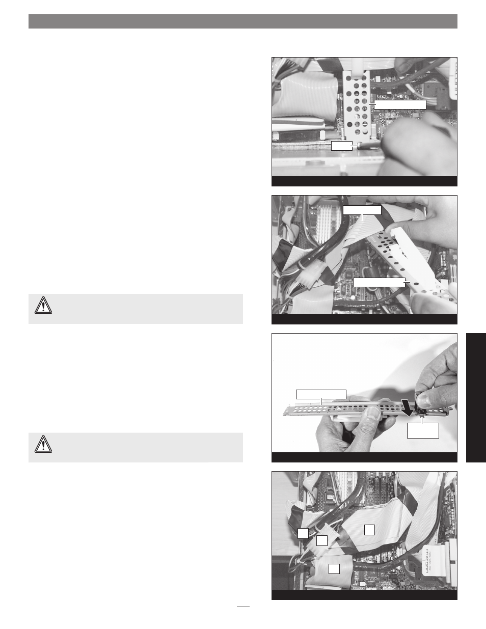
3. Remove the screw securing the cable support bracket to the rear
panel
(Figure 41); be careful not to lose the screw when removing it,
as it can easily drop into the chassis carrier.
4. Carefully remove the cable support bracket from the chassis car-
rier
(Figure 42).
5. Slide the brass-colored spring clip off of the cable support brack-
et, and then set it, the bracket, and the screws aside
(Figure 43);
do not reinstall the spring clip.
Disconnect Logic Board Cables
In order to install the Encore/ZIF processor upgrade card and its
included power adapter cable, you will need to disconnect various
connectors, and unplug cables from the logic board first.
Figure 44
identifies the cables and the order in which they should be disconnected.
• Internal drives power cable connectors
(A)
• Main SCSI cable
(B)
• Secondary SCSI cable
(C)
• Logic board power cable
(D)
WARNING:
When disconnecting cables from the logic board,
do not pull on the wires; always pull on the connectors or
their pull tabs.
screw
cable support bracket
main SCSI cable
cable support bracket
cable support bracket
remove
spring clip
A
D
C
B
WARNING:
You must remove the spring clip from the cable
support bracket, otherwise the Encore/ZIF card will be dam-
aged when you reassemble and attempt to operate your computer.
G3
A
ll-
in
-o
ne