Ransburg, Micropak - operation, Canbus address – Ransburg MicroPak LECU5004 User Manual
Page 18: Di/dt operating mode, Micropak di/dt sensitivity levels
MicroPak - Operation
Ransburg
15
LN-9218-00.13
CANBus Address
The MicroPak must be set at a non-zero CANBus
address when CANBus communication is used,
whether from an outside CANBus source, Discrete
I/O Module or Node Adapter.
When front panel controls are used, SW3-3 can
be set to OFF so that the HV ON mode is always
enabled, meaning that anytime the HV Ready
mode is entered, HV is turned on. This allows
the front panel kV switch to enable the HV Ready
and HV On modes at the same time.
The address is set in binary by Switch SW7, la-
beled “Node Address”, positions 2-4 with position
4 being the LSB (see Figure 6). In applications
where Discrete I/O Module is used, the MicroPak
must be set at CANBus address 01. In Node
Adapter applications, the MicroPak(s) must be
set to a CANBus address corresponding to the
locations in the PLC I/O tables. Each MicroPak
must have a unique address from 01-04.
Di/dt Operating Mode
A di/dt (rate of change in current with respect to
time) safety overload function can be used in
addition to the fixed current overload. This is an
adjustable setting which determines the maximum
current increase that can occur during a fixed
time period.
The di/dt detection feature will improve the ability
of the power supply to prevent discharges to the
applicator when a grounded object is approaching
at rates greater than approximately 4 inches per
second. Slower rates of approach are typically
sensed by the fixed current overload if properly
set. The di/dt and fixed current overloads must
be set correctly to prevent discharges when using
metal (unlisted) applicators.
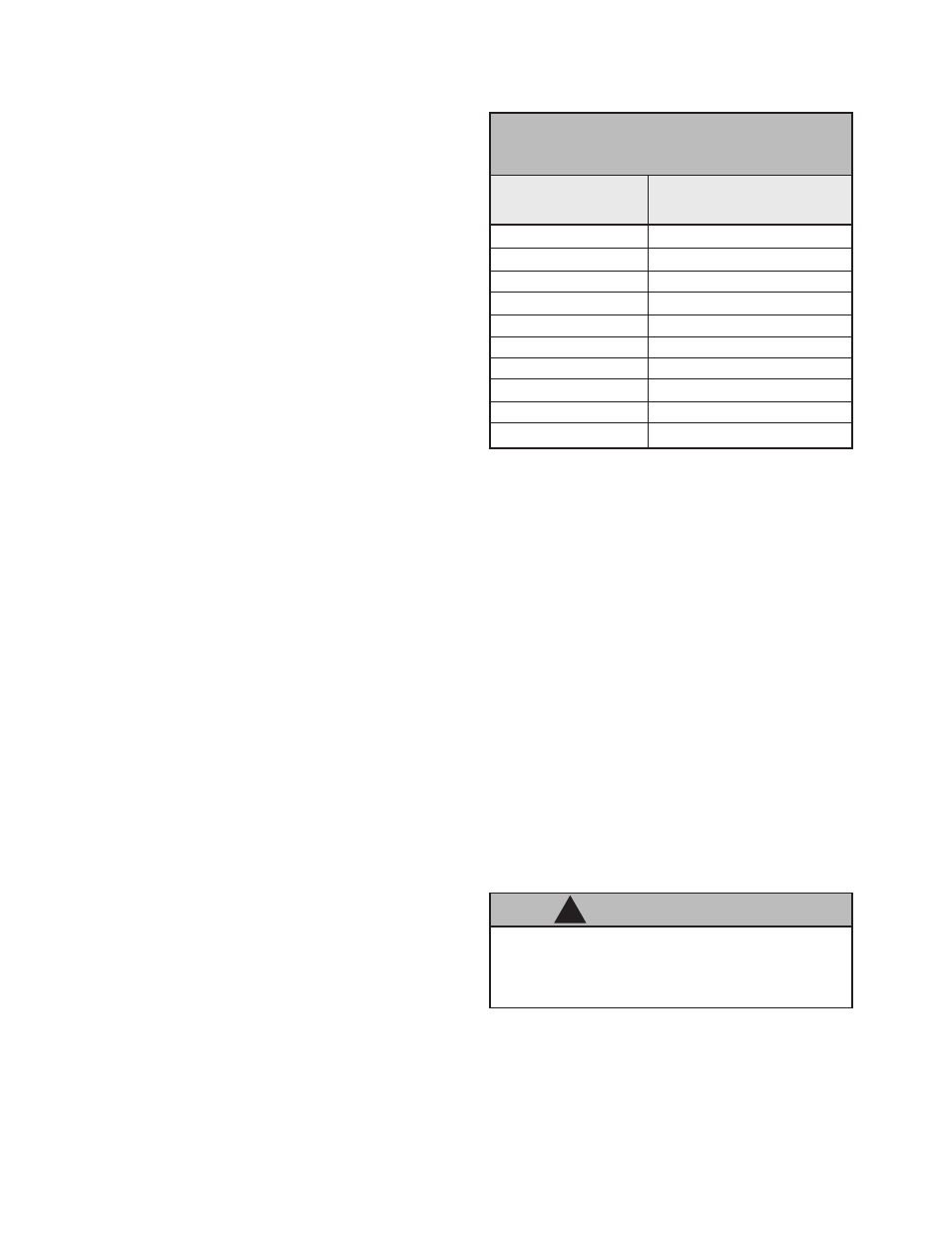
The MicroPak controller monitors the output
current and compares the value to the rate of
change set- point (SLP) provided by the user set-
ting. (See the “MicroPak Di/dt Sensitivity Chart”
for corresponding rates of change for each SLP
setting number.)
8.0
10.0
15.0
20.0
25.0
30.0
35.0
40.0
50.0
60.0
SLP #
Sensitivity
µA/100m Sec.
MICROPAK di/dt
SENSITIVITY LEVELS
0
1
2
3
4
5
6
7
8
9
Separate ground connections
MUST be
used for grounding the part and the Power
Supply.
The di/dt overload is disabled for the time required
to ramp voltage from a lower requested kV to a
higher value. This time will vary based on the
magnitude of the kV increase. The HV “ON” LED
will flash ON and OFF during each di/dt inhibit
period (Local mode only).
When the applicator is moved quickly (e.g., ro-
bot), SLP #7, #8 or #9 should be used to avoid
nuisance faults.
For di/dt modes of operation, the di/dt function is
enabled by setting SW7-6, located on the Micro-
Pak Process PCB to the ON (down position). For
all other applications where di/dt does not apply,
SW7-6 must be set to the OFF (up) position. This
is the default setting for all MicroPak control unit
models that do not have the di/dt function.
C A U T I O N
!