Ransburg, Aerbell 33 rotary atomizer - operation – Ransburg Aerobell 33 AER5000, AER5001 User Manual
Page 19
Aerbell 33 Rotary Atomizer - Operation
Ransburg
15
LN-9521-00.4
color change requirements may necessitate the
use of both ranges. If color change time is not
a factor or if material viscosity remains relatively
constant, either port may be used depending on
flow rate requirements.
The high flow port characteristics are similar to
those found in most commercially available, air
operated fluid regulators. Fluid regulation from
the high flow port is therefore comparable in total
flow capacity, although consistency of flow is im-
proved considerably when using a regulator. All
regulators, regardless of ratio designation, have
the high flow port.
The low flow (i.e. 1:2, 1:4, etc.) port provides a
lower, more precise flow response curve. Fluid
output, as a result, is less likely to be affected by
pilot signal errors. An increase in the ratio (i.e.
from 1:2 to 1:4) provides a lower slope, but, more
precise response curve. This same increase
in ratio, however, will reduce flow capacity and
should be considered when selecting the proper
regulator ratio.
The following factors must then be considered
when selecting the regulator ratio required for
proper fluid control:
• Maximum fluid output requirements (Guide:
10 psi minimum, 30 psi max.)
• Fluid tubing inside diameter (ID) and length
• Fluid feed tube inside diameter (ID) and length
• Fluid viscosity
• Fluid input pressures (Guide: 10 psi above
max. fluid output pressure)
Only proper testing will determine which regulator
ratio should be used. If conditions change after
installation which require a different low flow ratio,
this regulator can be altered easily by replacing
the existing ratio spacer ring and upper retainer
with the desired ratio (ratio designation is etched
on the side of the spacer ring).
The output of the regulator is externally connected
to a fitting on the fluid manifold assembly. The
fluid manifold assembly is equipped with valves
which are pneumatically operated to direct the
flow of paint to either the feed tube or dump line
and to supply a intermittent solvent bell wash for
the feed tube and bell cup.
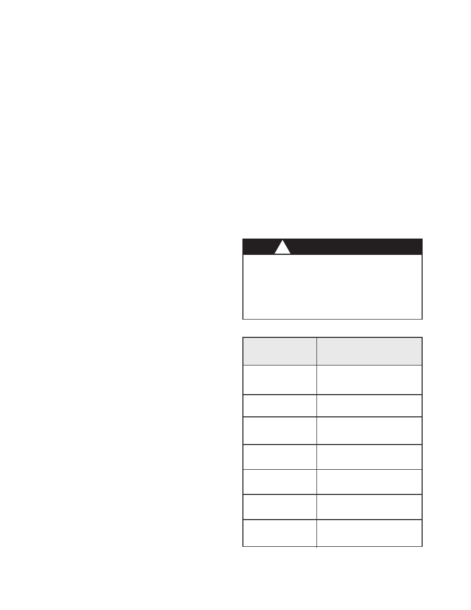
Figure 10: Fluid Regulator Selections
Low Flow Rates
1:1
1:2
1:3
1:4
1:6
1:8
1:10
Fixed Atomizer
Regulator Part No.
LREG5001-01
LREG5001-02
LREG5001-03
LREG5001-04
LREG5001-06
LREG5001-08
LREG5001-10
W A R N I N G
Danger of shock and/or personal injury
can occur. Proper grounding procedures
must be followed. Personnel must never
work around the turbine when the turbine is
spinning or when high voltage is turned on.
!
The feed tube is available in several sizes (See
Figure 11). The viscosity and volume of the coat-
ing material being sprayed determine the correct
size of feed tube for each installation. The feed
tube diameter acts as a linear restrictor to create
back pressure on the fluid regulator so that it can
provide accurate and repeatable flow to air signal
resolution.
Fluid Flow Rate Check:
In test mode, the flow rate can be measured by
removing the bell cup from the atomizer, turning
the fluid flow on and capturing the material in a
graduated beaker or measuring cup for a fixed
period of time (shaping air, high voltage and tur-
bine air must be off).