Kasco Marine Pond Aerator & Water Circulator User Manual
Page 8
8
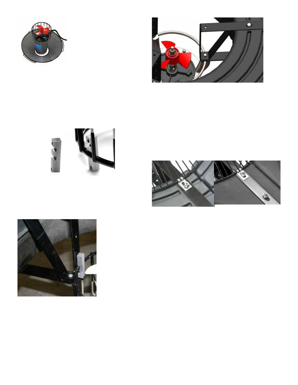
STEP SEVEN (Optional Bottom Screen)
Raise the Bottom Screen and secure with Bottom
Screen clips. Remove the center three 3/8” Lock Nuts
from the 9” Bolts and place the Bottom Screen Clips
(Part #B10) over the bolts as shown. The power cord
can be slid under the bottom screen between the float
and screen where two float sections come together
before the 3/8” Lock Nuts are replaced. Replace the
three inside Lock Nuts and tighten all 3/8” Lock Nuts
using the 9/16” wrench and socket.
Note: Extra hardware may be included
STEP EIGHT
On power cord lengths of 100 feet or longer with
the watertight Quick Disconnect, the power cord is
shipped separately. It should now be attached to the
stub cord by lining up the male and female halves of
the disconnect and hand tightening the blue collar. On
these cords, the Additional Strain Relief should be
attached to one of the lower float brackets as pictured.
If you receive a 3 chain strain relief (6 or 8 gauge
cord), attach one chain to each of the three lower float
brackets. If there is not Strain Relief, use the Nylon
Cable Tie provided to secure the cord to a rope to
prevent damage by the propeller. Double check the
Quick Disconnect to make sure the threaded collar has
not come loose in shipping before placing in the water.
If installing a new Quick Disconnect, please refer to
Quick Disconnect instructions.
STEP SIX (8400,2.3)
Lift Float Assembly and place over Aerator Assembly.
Adjust one unit Mounting Bracket at a time and nest
the cage ring in the lower notch of the Unit Mounting
Bracket for the 3.1, and 5.1 units. Nest the cage ring
in the middle notch of the Unit Mounting Bracket for
the 8400.
8400, 2.3
Once all three Unit Mounting Brackets are seated
correctly on the cage ring, add remaining 1/4” x 3/4”
Bolts and 1/4” Lock Washers to lower mounting hole.
Tighten all bolts on the Unit Mounting Bracket with
7/16” socket or wrench.
STEP SIX (3.1, 3.3, 5.1, 5.3)
Lift Float Assembly and place over Aerator Assembly.
Place the 3/8” x 1” Bolts (Part #B6) and 3/8” Lock
Washers (Part #B7) through the top float bracket and
lower float bracket as shown and screw directly into
the aerator mounting ring. Tighten down with a 9/16”
wrench.