Kasco Marine Pond Aerator & Water Circulator User Manual
Page 17
17
minutes for each tripper on the 24-Hour dial. When
the tripper is pushed to the inside, the switch is in the
“OFF” position.
PROGRAMMING WITH MANUAL OVERRIDE
SWITCH
Your Timer may have a 3-way manual switch or a
2-way manual switch.
AUTOMATIC MODE
In order to operate the time clock in the automatic
mode, the manual switch must be in the automatic
postion- see diagram.
MANUAL MODE
For the 3-way switch, with the manual override switch
in the lower position, marked “O”, the time clock
output will remain Permanently OFF. In the upper
position, marked “I”, the time clock output will remain
permanently ON.
For the 2-way switch, with the manual override switch
in the lower position, marked “ON” the time clock
output will remain permanently ON.
TIME SETTING
TO SET THE CURRENT TIME (AND DAY OF WEEK
ON 7 DAY UNITS), TURN THE MINUTE HAND
CLOCKWISE. DO NOT SET THE TIME BY ROTAT-
ING “OUTER” DIAL.
Turn the minute hand clockwise until the day of the week
(7-day timer) and the time of day on the outer dial is
aligned with the triangle marker on the inner dial (two
o'clock position).
Example for 7-day program dial Monday 10:30 AM. Turn the
minute hand clockwise until Monday 10:30 AM is aligned
with the triangle on the inner dial. The hour and minute hand
will show exactly 10:30.
Example for 24-hour program dial 10:30 AM. Turn the minute
hand clockwise until 10:30 AM is aligned with the triangle on
the inner dial. The hour and the minute dial will show exact-
ly 10:30.
PROGRAMMING
7-Day (SW, QRW Models)
The weekly program dial reflects the seven days of the week
and AM/PM imprints for each day.
The time switch is programmed by pushing the captive trip-
pers to the outer ring position for the entire period that the
load is to be turned “ON”, i.e., two hours for each tripper on
the 7-Day dial. When the tripper is pushed to the inside, the
switch is in the “OFF” position.
24-Hour (ST, QRT Models)
The 24-Hour dial has quarter-hour divisions and AM/PM indi-
cations.
The time switch is programmed by pushing the captive trip-
pers to the outer ring position for the entire period that the
load is to be turned “ON”, i.e., fifteen minutes for each trip-
per on the 24-Hour dial. When the tripper is pushed to the
inside, the switch is in the “OFF” position.
PROGRAMMING WITH MANUAL
OVERRIDE SWITCH
AUTOMATIC MODE
In order to operate the time switch module in the automatic
mode, the manual switch must be in the center position (auto-
matic) - see diagram.
MANUAL MODE
With the manual switch selector lever the selected programs
can be overridden. In the lower position, marked “O”, termi-
nals 3 and 5 are permanently closed. In the upper position,
marked “I”, terminals 3 and 4 are permanently closed (see
diagram).
300GR10020
Override Mode
3-way manual
override switch
I = permanent ON
= automatic
0 = permanent OFF
Dimensions
FM/1 synchronous/quartz
Intermatic Incorporated • Spring Grove, IL 60081 • www.intermatic.com
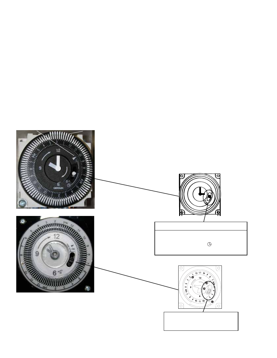
ON
AUTO
SETTING THE TIMER
The timer is a 24 hour time clock with 15 minute increment settings.
The captive trippers change the SPDT relay state when pushed
toward the outside.
1. Setting time of day
(a) Synchronize the timer by aligning arrow at the 2:00 position
of inner face with the corresponding time of day printed on the
outer ring.
NOTE: Power must be ON to keep time synchronization.
2. Setting ON time and duration
Locate desired activation time(s) on outer ring
(b) and push
trippers to the outside
(c). Each tripper represents 15 minutes
activation time. Push as many trippers back as desired for dura-
tion time. When the timer reaches the fi rst tripper, the timer SPDT
contacts will change state and turn ON. It will remain ON for as
long as the following trippers are pushed out. When timer goes
past last tripper, the timer will return to the
OFF mode. The timer
has a selector for
(d) AUTOMATIC and ON modes.
Overide Mode
2-way manual
ON - Permanently ON
overide switch
AUTO - automatic
C85 / C95 non-metallic and 3 Phase
Control Panel Timer
TIME CLOCK SETTING
To set the current time, turn the inner dial clockwise.
Do not set the time by rotating “outer” dial.
Turn the minute hand or small plastic inner dial clock-
wise until the time of day on the outer dial is aligned
with the triangle marker on the inner dial (two o’clock
position).
Example for 10:00 AM. Turn the minute hand clock-
wise until 10:00 AM is aligned with the triangle on
the inner dial. The hour and the minute dial will show
exactly 10:00.
Triangle marker
Captive trippers
(in the on position)
PROGRAMMING
The 24-Hour dial has quarter-hour divisions and AM/
PM indications.
The time switch is programmed by pushing the captive
trippers to the outer ring position for the entire pe-
riod that the aerator is to be turned “ON”, i.e., fifteen