Kasco Marine Pond Aerator & Water Circulator User Manual
Page 7
7
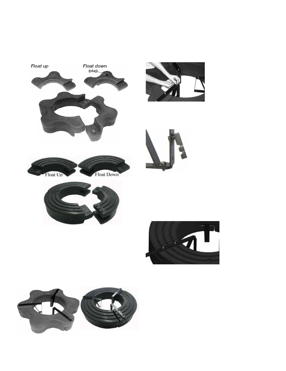
Float Brackets (Part #B3) over the bolts, the ends of
which should now be extending through the assembly.
Loosely install the six 3/8” Lock Nuts (Part #B5) on
the ends of the bolts (do not tighten yet). Connect the
Top and Bottom Float Brackets using three 1/4” x 3/4”
Bolts (Part #B9) with three lock washer and 1/4” nuts
and tighten using the 7/16” wrench and socket.
Attach the Unit Mounting Brackets (Part #B6) loosely
to the float bracket with (3) 1/4” x 3/4” bolts and 1/4”
Lock Washers in the top mounting hole as shown
STEP FOUR (3.1, 3.3, 5.1, 5.3)
Turn the assembly upside down and place the Bottom
Float Brackets (Part #B3) over the bolts, the ends of
which should now be extending through the assembly.
Loosely install the six 3/8” Lock Nuts (Part #B5) on
the ends of the bolts (do not tighten yet).
STEP FIVE
See “Mesh Screen Attachment” section before con-
necting the bottom screen to the float.
If the optional Bottom Screen (Part#B11) was pur-
chased, place the Aerator Assembly inside the bottom
Screen as shown.
immediately.
STEP TWO
Arrange the three Float Sections (Part #B1) upright
(plug on bottom) so the overlap of one section aligns
with the next section and loosely push the three sec-
tions together to form a continuous ring.
8400AF, 2.3AF
3.1AF, 3.3AF, 5.1AF, 5.3AF
STEP THREE
Position one Top Float Bracket (Part #B2) so that the
bolt holes in the bracket align with the bolt holes in the
two adjoined float sections and insert two 9” Coated
Bolts (Part #B4) through the assembly. This may
require some minor repositioning of the float sections
as you push the bolt all the way through. Do not force
the bolt through. Repeat for the remaining two joints.
STEP FOUR (8400, 2.3)
Turn the assembly upside down and place the Bottom