Kasco Marine Pond Aerator & Water Circulator User Manual
Page 5
5
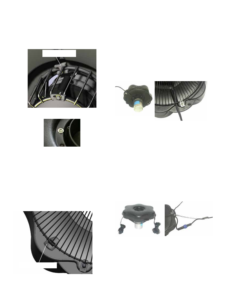
STEP SIX (optional bottom screen)
Using a stainless steel Bottom Screen Clip (Part 11),
3/8”-16 x 1-3/8” Bolt (Part 7), two 3/8” Flat Washer
(Part 8), and 3/8”-16 Nylon Lock Nut (Part 12) to
secure the screen to the float. Align a clip so the two
prongs straddle a wire on the screen. Insert bolt with
washer so the top of the bolt is facing the top of float
(now in down position). Place the second washer and
the locking nut with nylon insert on the end of the bolt
and tighten using the 9/16” (14mm) Socket and Ratch-
et on the nut end and the 9/16” (14mm) Wrench on the
bolt end. Tighten until snug and repeat with remaining
clip.
STEP SEVEN
Turn the assembly upright again. At this time, if the
cord contains a metal strain relief, you can use the
chain connector and attach it in one of the opening at
the rope placement. The chain connector will easily fit
if installed from the bottom or top side of the opening.
It will not fit if installed from side of opening. Use the
Nylon Cable Tie included to secure the power cord to
a molded hole in the float to prevent cord damage if
there is no strain relief on the cord. If a Strain Relief
is present on the cord, you may disregard the Nylon
Tie. On cords with a Quick Disconnect, the discon-
nect should be tightened properly to avoid leaking.
If installing a new Quick Disconnect, refer to Quick
Disconnect Instructions.
STEP EIGHT(optional)
Thread one rope through one Pipe Weight and posi-
tion it approximately 6’ from the float. Next, thread
the end of the rope back through the opening facing
the float (as shown). Repeat with the second rope and
weight. If ready to install in the pond, go to Instal-
lation instructions. Light Kits can also be installed at
the flat washer. Insert screw with washer through bolt
hole in float
Use one float retaining clip (Part 6) under the top ring
of the cage. There is a U-shaped indent in the clip that
will fit snug against the top ring of the cage. The 1/4”-
20 x 3-1/2” will then thread into the retaining clip.
float retain
ing clip
Tighten until snug with a Phillips Head screw driver
and repeat for 3 remaining screws.
STEP FIVE (optional bottom screen)
See “Mesh Screen Attachment” section before con-
necting the bottom screen to the float. Turn secured
assembly upside down so the top of the float (logo
side) is face down on the flat surface. Place Bottom
Screen (Part 10) onto the bottom side of the float.
Make sure the wide opening of the screen is against
the float and the 3 handles on the screen do not in-
terfere with the rope placements. Fit the 3 Bottom
Screen cushion (Part 9) underneath the screen and on
top of the 3 spacing bumps on the bottom of the float.
Bottom Screen cushion