Control panel installation – Kasco Marine Pond Aerator & Water Circulator User Manual
Page 12
12
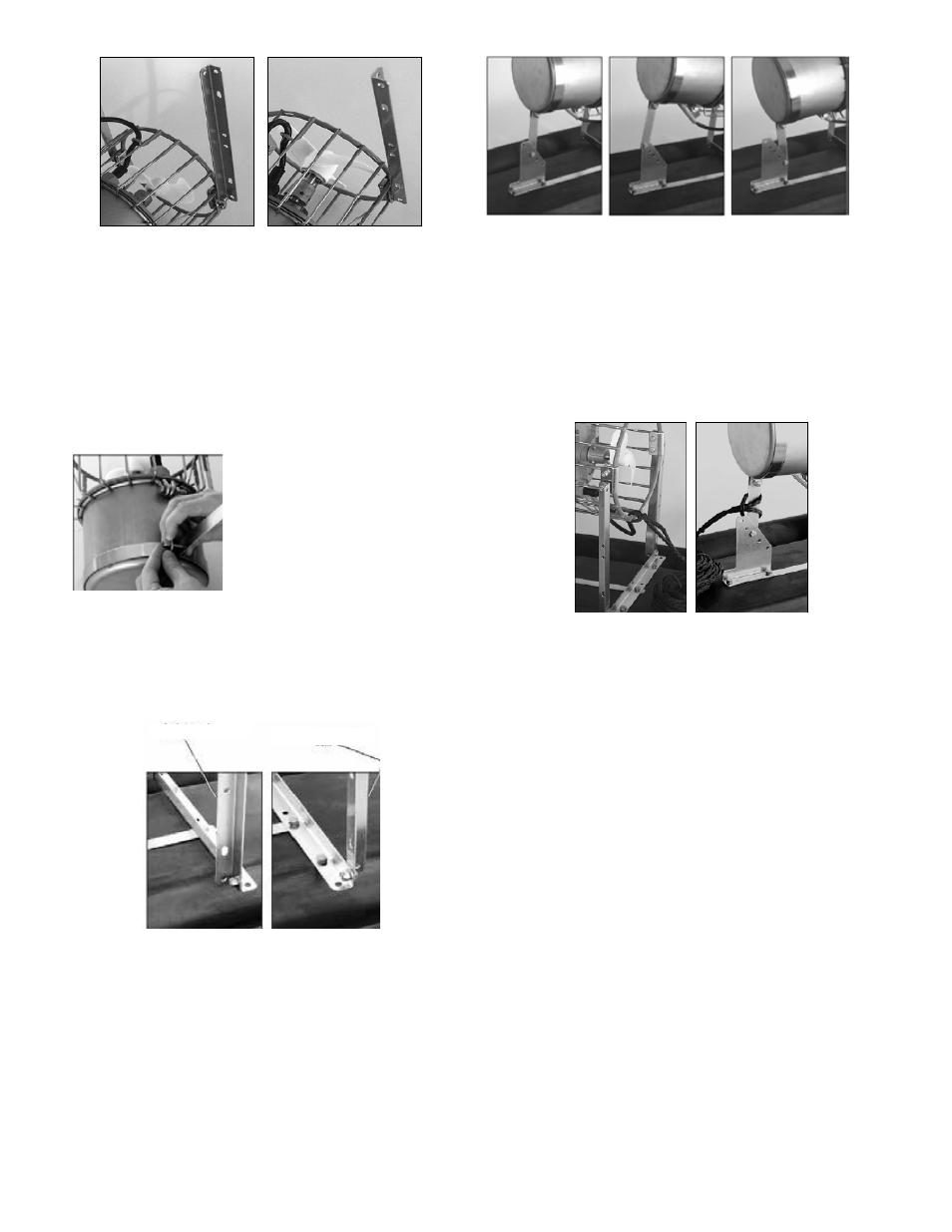
2400 & 3400
4400 & 8400
STEP NINE
Wrap the Draw Band (Part B5) around the motor housing
and position so that the back of the Draw Band touches the
marks drawn in Step Five. There is no front or back to the
Draw Band itself - it is reversible. Orient the arm of the
Draw Band so it aligns with the cord clamp on the cage
of the motor housing and is parallel to the Angle Brackets
attached in Step Eight. Secure using a 1/4” x 1” Stainless
Steel Bolt and a 1/4” Lock Nut. (See photo in next column)
STEP TEN
Attach the Angle Bracket on the motor to the Angle Bracket
on the Float using two 1/4” x 1/2” Bolts and two 1/4” Lock
Nuts (one set for each Bracket). See photos for orienta-
tion based on model size. Also, the cord clamp on the cage
should be oriented toward the Float.
2400 & 3400
4400 & 8400
Angle towards back
Angle Towards front
STEP ELEVEN
Attach the Draw Band on the motor to the Adjustment
Bracket on the Float using a 1/4” x 1/2” Bolt and a 1/4”
Lock Nut. Select one of the five possible positions to
mount the Draw Band for your preferred direction of flow.
We do not recommend the two outer (most upward and
most downward) mounting positions for 8400 models.
Horizontal
Angled Up
Angled Down
STEP TWELVE
Attach the Ropes to the front (on the cage) and back
(around the Draw Band) of the motor. At this time, use the
Nylon Tie provided to connect the power cord and front
Rope to prevent the cord from tangling in the prop. Also,
if the power cord has a Quick Disconnect and Additional
Strain Relief install the Quick Disconnect and Strain Relief
per instructions.
STEP THIRTEEN
Float the circulator in the water and position where desired.
Tie the front Rope to a stake on the shore or weight. If a
weight is used sink weight in front of unit so rope is taught.
(Circulators create great force, make sure weight is enough
to prevent movement.) Tie back Rope to a stake on oppo-
site shore or weight. Sink weight behind the unit so rope is
taught. At this time take up any slack in the line.
STEP FOURTEEN
You can now connect the Circulator into the GFI pro-
tected power source at the ponds edge.
Control Panel Installation
STEP ONE
Inspect the panel for any damage and any components that
may have loosened during shipping.
Control panel must be installed a minimum of 5ft (3m in
Canada) from the inside wall of the pond, unless separated
from the body of water by a fence wall, or other permanent
barrier that will make the unit inaccessible to persons in the
water.
Install the control panel to a post structure, side of a