Logo – Kasco Marine Pond Aerator & Water Circulator User Manual
Page 4
4
tional C-25 (3) or C-85 (4)
• 9/16” Socket and Ratchet (for optional bottom
screen)
• 9/16” Wrench (for optional bottom screen)
• Nylon Tie for cord
2400AF, 3400AF/HAF, 4400AF/HAF Assembly
STEP ONE
Make sure you have all the parts needed. If any short-
ages are found, contact your Kasco representative
immediately.
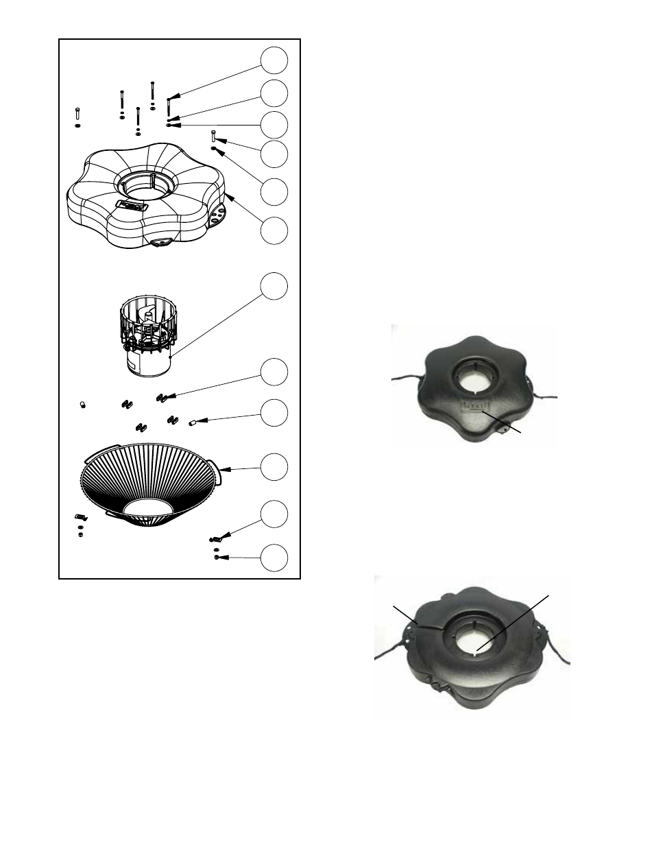
STEP TWO
Set motor housing upright (stainless steel can down)
on a flat surface. With motor housing upright, slide
Float (Part 2) over pump housing making sure the
surface with the Kasco logo is up.
logo
Rest the float on the cage top ring.
STEP THREE
Ensure correct alignment by twisting the float gently
around the motor housing until the power cord guide
lines up with the cord. See diagram of bottom side of
float.
Bolt holes
power cord
guide
STEP FOUR
Use one of the 1/4”-20 x 3-1/2” Phillips Pan Head
Screws (Part 3), one 1/4” split washer (Part 4), and a
1/4” Flat Washer (Part 5) to secure the float. Make
sure the split washer goes between the bolt head and
1
2
3
4
5
7
8
6
9
10
11
12
REV.
ECO#
DESCRIPTION
DR'N BY
DATE
DES ENG CH'K BY
1
INITIAL RELEASE
XXXX-XXXX-XX
DO NOT SCALE DRAWING
C.A.D. GENERATED DRAWING
800 DEERE ROAD
PRESCOTT, WI 54021-1241
X
FX FLOAT ASSEMBLY W/SCREEN
X
X
X
X
THIS DRAWING CONTAINS PROPRIETARY
INFORMATION AND SHALL NOT BE USED,
REPRODUCED OR DISTRIBUTED WITHOUT
THE PRIOR WRITTEN CONSENT OF
KASCO MARINE, INCORPORATED
.X .02 [.508] .XX .010 [.254]
.XXX .005 [.127] ANGULAR 0.5
UNLESS OTHERWISE SPECIFIED
DIMENSIONS ARE IN INCHES.
DIMENSIONS IN [ ] ARE MILLIMETERS.
TOLERANCES ON:
THIS DOCUMENT HAS BEEN ISSUED
FOR ENGINEERING INFORMATIONAL
PURPOSES ONLY. ANY REVISIONS
TO THE CONTENT OF THIS DOCUMENT
MUST BE INCORPORATED INTO THE
ORIGINAL CAD FILE.
THIRD ANGLE PROJECTION
TITLE:
XXXX-XXXX-XX
SHEET 1 OF 1
FINISH:
MATERIAL:
SCALE: 1:24
DWG. NO.
Optional Equipment
• Control Box (C-25 for 120V units or C-85 for 240V
units in separate box) (1 - optional)
• Bottom Screen with mesh and Hardware for Small
Float Ring (1 - optional)
NOTE: Extra hardware may be included.
POND AERATOR TOOLS & SUPPLIES NEEDED
• Anchors or stakes for installing unit (2 or 3 depending
on unit)
• # 2 Phillips head screw driver
• Two (or 3 depending on model) 12” pieces of 1” galva-
nized pipe for weighting ropes (optional)
• #10 x 1” long or longer screw(s) for mounting the op-