Setup instructions, Operating instructions – General Tools and Instruments CIH20DL User Manual
Page 8
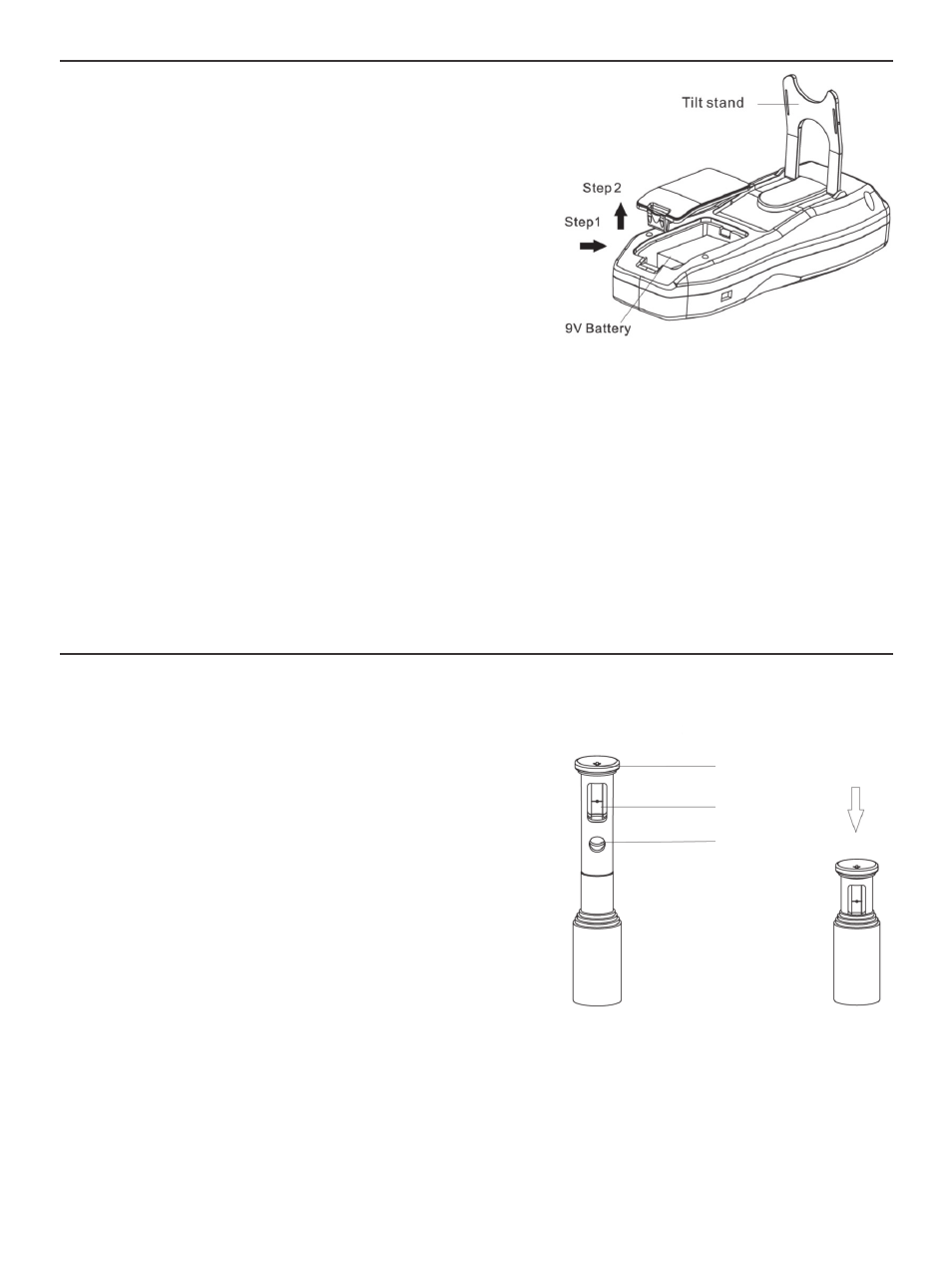
SETUP INSTRUCTIONS
INSTALL BATTERY
The meter’s battery compartment is accessible
from the back of the unit (Fig. 3).
Before installing the 9V battery included in the
carrying case, remove the plastic covering its
terminals. Open the battery compartment by
pushing the tab at the bottom of its cover forward
(Fig. 3, Step 1). Lift the cover and set it aside
(Step 2). Then plug the battery into the wired
socket inside the compartment. The terminals of
the battery and the socket mate in only one way,
with the smaller male terminal plugging into the
larger female terminal. Replace the battery compartment cover and push down on its bottom
until it snaps shut.
The CIH20DL also can be powered by connecting it to an AC outlet or a computer's USB port.
There is no reason to do so unless you plan to use the meter for extended data logging
sessions. Connecting the meter to an external power supply does not charge the included
“9V” Alkaline battery, which is not rechargeable.
See “Data Logging with a Computer”, beginning on p. 14, for ways to connect the CIH20DL
to an external power source.
OPERATING INSTRUCTIONS
GETTING STARTED
To prepare the CIH20DL for use, line up the hot wire
probe plug (Fig. 1, Callout 15) with the hot wire probe
socket on the top of the meter (Callout 11) so the
black arrow on the probe connector faces the back of
the meter. Then insert the probe plug into the socket.
Before extending the telescoping probe, extract
the probe head (Callout 14) from the probe body
by grasping the round black plastic end piece
(Fig. 4 left, top callout) with two fingers and pulling
slowly. Take care not to touch either the hot wire air
speed sensor or the air temperature sensor within
the head; both are extremely delicate. Pull out the
probe head to expose 1 inch of probe body. Exposing
the probe head now will allow you to telescope the
probe to any length later by grasping its body rather than its delicate head.
Following each measurement session, carefully push the probe head back into the probe
body (Fig. 4, right) in order to protect the sensors.
8
Ready For Use
Not in Use
Black plastic
end piece
Hot wire air
speed sensor
Air temperature
sensor
Fig. 3. The back of the CIH20DL
Fig. 4. The probe head assembly
CIH20DL-FINAL-122111_awb 12/21/11 9:58 AM Page 8