Operation, The fulton companies 2013, Water header honeywell header sensor and well – Fulton Pulse HW (PHW) Fully Condensing Hydronic Boiler User Manual
Page 58
© The Fulton Companies 2013
OPERATION
PHW-IOM-2013-0214
SECTION 3
3-22
J3 ECOM 1,2,3
For Outdoor
Sensor Interface
Module
J8 (S5) terminals
11 & 12 For
Header Sensor
POWER
FLAME
ALARM
RESET
2-40-000907
BOILER
Master
A B C
J3 (MB1) A,B,C
For daisy chain of
boilers
Com 1 and 24
VAC of the
display will be
pre-wired at the
factory
S7999D
Display
POWER
FLAME
ALARM
RESET
2-40-000907
BOILER
Lag
A B C
J3 (MB1) A,B,C
For daisy chain of
boilers
Com 1 and 24
VAC of the
display will be
pre-wired at the
factory
S7999D
Display
POWER
FLAME
ALARM
RESET
2-40-000907
BOILER
Lag
A B C
J3 (MB1) A,B,C
For daisy chain of
boilers
Com 1 and 24
VAC of the
display will be
pre-wired at the
factory
S7999D
Display
COM 1
1
COM 2
24 VAC
A
B
C
A
B
C
COM POWER
COM 1
1
COM 2
24 VAC
A
B
C
A
B
C
COM POWER
COM 1
1
COM 2
24 VAC
A
B
C
A
B
C
COM POWER
C
la
m
p
Fi
lt
er
TE
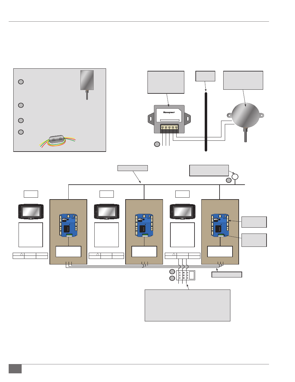
Water Header
Honeywell Header
Sensor and Well
Outdoor Sensor Interface Module
1
2
3
OT
OT
Communication wire, Modbus for BMS
RS-485 message format:
1 start bit
8 data bits
No parity bit
1 stop bit
Note: If boilers are daisy chanied together only one BMS
connection is required to the master.
Communication wire
Outside
Wall
Outdoor Sensor
Interface Module,
mounted inside as
close to outdoor
sensor as possible
Honeywell Sensor and Well
Outside Air Sensor
2 wire, landed on
“OT” of interface
Module, Field Wiring
Ou
td
oo
r S
en
so
r
1
3 Wires Connected to Master Boiler
(J3 ECOM terminals 1,2 and 3), Field Wiring
2
Field Wiring
3
Clamp Filter all connections to D display
4
4
3
1
2
He
ad
er
Se
ns
or
FIGURE 51 - LEAD/LAG OF HYDRONIC BOILERS USING THE SOLA CONTROL (MAXIMUM OF 8 BOILERS)