Installation – Fulton Pulse HW (PHW) Fully Condensing Hydronic Boiler User Manual
Page 33
Questions? Call (315) 298-5121, or visit us online at www.fulton.com
SECTION 2
PHW-IOM-2013-0214
INSTALLATION
2-27
shutoff valve for the pressure reducing (fi ll) valve, and
all manual air vents.
2. Open all other system shutoff valves one of the zone
valves, the vent on the combination shutoff / purge
valve, and the shutoff valve to the pressure reducing
(fi ll) valve.
3. Water will now begin to fi ll the system. Air will escape
through the vent on the combination shutoff / purge
valve. Continue fi lling until a constant stream of water
(no bubbling) is discharged from the vent.
4. Close the zone valve on the purged loop, and open the
zone valve on the next loop to be purged. When all air
has escaped and only water is discharged, close the
zone valve. When all zones have been purged. (one at a
time), close the vent on the combination shutoff / purge
valve.
5. At this point, the system has been initially fi lled.
However, air pockets may still remain at high points
in the system and in heating loops above the level
of the combination shut/off purge valve. It is quite
possible, depending on the particular system that all
RETURN FROM
SPACE HEATING SYSTEM
DRAIN
9
13
10
12
11
10
9
7
14
*
*ALTERNATE LOCATION
COLD
WATER
SUPPLY
BOILER
1
2
3
4
5
7
8
6
HIGH POINT
AIR VENT
VENT
(TYPICAL)
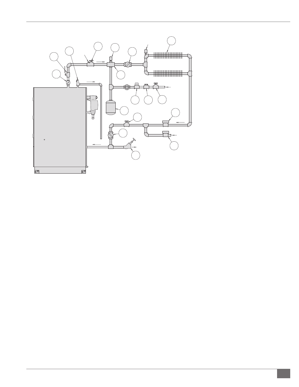
FIGURE 21 - PURGE EXAMPLE
Legend:
1. Temperature/ Pressure
Indicator
2. Hot Water Outlet Stop Valve
3. Safety Valve
4. Combo Shutoff / Purge Valve
5. Auto Air Vent
6. Air Scoop
7. Circulator
8. Heat User
9. Zone Valve
10. Stop Valve
11. Check Valve
12. Pressure Reducing Valve
13. Diaphragm Expansion
Tank
14. Drain Valve
piping above the combination shutoff /purge valve still
contains air. If manual vents are installed on the system
high points, these should be opened to vent these
locations. When only water is discharged from all vents,
the initial purging is complete.
6. Open the combination shutoff / purge valve (keep the
vent closed). With the gas shutoff valve closed, turn on
power to the boiler and operate the circulator. Circulate
the system water for approximately 30 minutes to move
all air to the automatic air separation point.
7. Again, open manual air vents at high points of heating
loop until a constant stream of water is discharged from
the vent. Close the vent and make sure it’s watertight.
Repeat procedure for all high points and for every zone.
8. Check temperature/pressure indicator reading, which
should equal the pressure reducing (fi ll) valve set
pressure. No more water should be entering the system.
Close the shutoff valve on the cold water fi ll line.
9. Visually inspect all pipe joints and equipment
connections for leaks. If necessary, drain system, repair
leaks and refi ll/purge the system. If no pressure drop is
detected for a period of two hours under pressure, the