Operation – Fulton Pulse HW (PHW) Fully Condensing Hydronic Boiler User Manual
Page 53
Questions? Call (315) 298-5121, or visit us online at www.fulton.com
SECTION 3
PHW-IOM-2013-0214
OPERATION
3-17
!
WARNING
All information in this manual is for
reference and guidance purposes,
and does not substitute for required
professional training, conduct,
and strict adherence to applicable
jurisdictional/professional codes and
regulations.
Non-Fulton product information is for
reference purposes only. No Fulton
document may substitute for full
review of documentation available
from the component manufacturer.
7. For the Slave Boiler(s), go to the Confi guration Menu, select Lead Lag Slave
Confi guration and select Slave Enable - Enable slave for built-in Lead Lag
Master. See Figure 41.
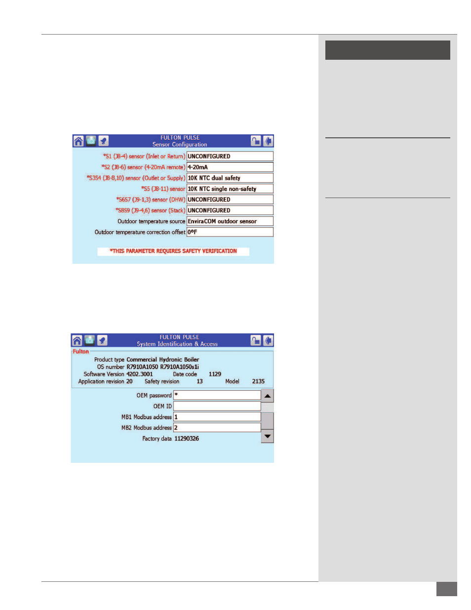
8. Master Boiler - Sensor Selection: In the Confi guration Menu go to Sensor
Confi guration. Press sensor Outdoor temperature source, select Enviracom
Outdoor Sensor. Also change S5 (J8-11) sensor to 10K NTC single non-
safety, this is your header sensor. See Figure 42.
9. Master and Slave Boiler - Back out to the Confi guration Menu and select
System Identifi cation and Access. See Figure 43. This is where the address
of each boiler will be selected at MB1 Modbus Address. The boilers will be
daisy chained to each other through MB1 on the base of the
FIGURE 43 - SYSTEM IDENTIFICATION AND ACCESS
control. The master boiler will be address 1 as shown in Figure 42. The
next “slave” boilers will be 2,3,4… depending on the amount of boilers.
Each boiler will have its own address.
10. Perform verifi cation of changes. See Figure 44.
FIGURE 42 - SENSOR CONFIGURATION