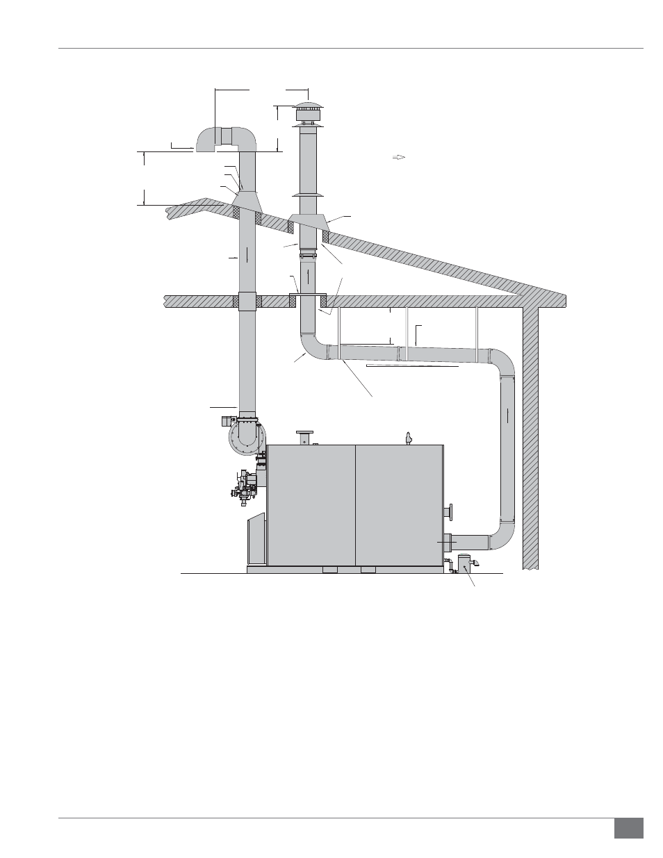
Installation, Typical roof penetrations, Figure 12 - roof penetration details – Fulton Vantage (VTG) Fully Condensing Hydronic Boiler User Manual
Page 29
Questions? Call (315) 298-5121, or visit us online at www.fulton.com
SECTION 2
VTG-IOM-2013-0815
INSTALLATION
2-23
the following items must be considered and addressed by the
parties responsible for designing and providing that system:
MULTIPLE BOILERS SHARING AN EXHAUST STACK, NEGATIVE
PRESSURE IN THE COMMON HEADER:
1. Precautions must be taken to ensure that the negative
pressure in the common header stays within the stated
ranges (refer to table 4) at all possible conditions. This
includes considering all possible operating conditions
of the stack, including:
All boilers on at their maximum input rating capacity
One boiler in the system on at a low fi re position
No boilers on, light off condition
2. Draft accessories, such as stainless steel dampers, may
be required depending on the variety of conditions
experienced in the draft system.
1/4" TAPPING FOR WATER
100 PSI MAXIMUM (U.S. ONLY)
ROOF
SUPPORT
4FT 3 IN
( 130 CM )
ADJUSTABLE
FLASHING
PVC PIPE
RISE TO RUN: 1/4" PER FOOT (2.12 CM/M)
METAL PLATE
FIRE STOP
MIN 4FT / 122 CM
ABOVE AIR
INTAKE PIPING
ADJUSTABLE
FLASHING
ADHESIVE SEAL
STORM COLLAR
SCREENED INLET
IF SNOW ACCUMULATION
IS APPLICABLE, OPENING TO BE
1 FT. / 30 CM ( MIN. ) ABOVE
THIS NORMALLY EXPECTED LEVEL.
TYPICAL ROOF PENETRATIONS
( SUGGESTED TERMINATION CONFIGURATIONS )
INSTALL SUPPORT STRAPS AT
5FT / 152CM HORIZONTAL
INTERVALS AND AT ELBOWS
EXHAUST
EXHAUST STACK IS DOWNWIND
OF AIR INTAKE OPENING
DO NOT PLACE INSULATION IN
REQUIRED AIR SPACE CLEARANCE
STAINLESS STEEL
HIGH TEMPERATURE
EXHAUST PIPE & FITTINGS
VANTAGE
HYDRONIC
BOILER
( SIDE VIEW )
NOTE:
AIR INTAKE AND EXHAUST TERMINATION SHOULD BE
SEPARATED AS FAR AS POSSIBLE TO PREVENT FLUE GAS
RECIRCULATION DURING DIFFERENT WIND CONDITIONS.
AIR INLET
MAINTAIN MIN 9" / 22.86 CM
AIR SPACE CLEARANCES
TO COMBUSTABLES,
WIRES AND INSULATION
PVC
90° ELBOW
FIGURE 12 - ROOF PENETRATION DETAILS