PASCO OS-9257A PRECISION INTERFEROMETER User Manual
Page 9
5
012-07137A
Precision Interferometer
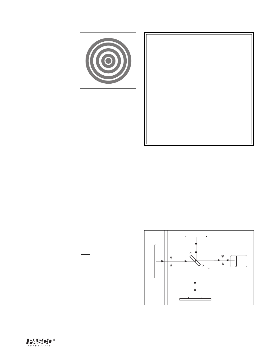
In this way the original
beam of light is split, and
portions of the resulting
beams are brought back
together. Since the
beams are from the same
source, their phases are
highly correlated. When
a lens is placed between
the laser source and the
beam-splitter, the light ray
spreads out, and an
interference pattern of dark and bright rings, or fringes, is
seen on the viewing screen (Figure 2).
Since the two interfering beams of light were split from the
same initial beam, they were initially in phase. Their
relative phase when they meet at any point on the viewing
screen, therefore, depends on the difference in the length
of their optical paths in reaching that point.
By moving M
1
, the path length of one of the beams can be
varied. Since the beam traverses the path between M
1
and
the beam-splitter twice, moving M
1
1/4 wavelength nearer
the beam-splitter will reduce the optical path of that beam
by 1/2 wavelength. The interference pattern will change;
the radii of the maxima will be reduced so they now
occupy the position of the former minima. If M
1
is moved
an additional 1/4 wavelength closer to the beam-splitter,
the radii of the maxima will again be reduced so maxima
and minima trade positions, but this new arrangement will
be indistinguishable from the original pattern.
By slowly moving the mirror a measured distance d
m
, and
counting m, the number of times the fringe pattern is
restored to its original state, the wavelength of the light (l)
can be calculated as:
l
=
2d
m
m
If the wavelength of the light is known, the same proce-
dure can be used to measure d
m
.
Figure 2. Fringes
The Twyman-Green Interferometer
The Twyman-Green Interferometer is a variation of the
Michelson Interferometer that is used to test optical
components. A lens can be tested by placing it in the beam
path, so that only one of the interfering beams passes
through the test lens (see Figure 3). Any irregularities in the
lens can be detected in the resulting interference pattern. In
particular, spherical aberration, coma, and astigmatism
show up as specific variations in the fringe pattern.
Figure 3. Twyman-Green Interferometer
Test
Lens
Lens
➤
NOTE: Using the Compensator
In Figure 1, notice that one beam passes through the
glass of the beam-splitter only once, while the other
beam passes through it three times. If a highly co-
herent and monochromatic light source is used,
such as a laser, this is no problem. With other light
sources this is a problem.
The difference in the effective path length of the
separated beams is increased, thereby decreasing
the coherence of the beams at the viewing
screen. This will obscure the interference pattern.
A compensator is identical to the beam-splitter, but
without the reflective coating. By inserting it in the
beam path, as shown in Figure 1, both beams pass
through the same thickness of glass, eliminating this
problem.