Michelson mode 1, Figure 5. aligning the laser, Figure 6. michelson mode setup – PASCO OS-9257A PRECISION INTERFEROMETER User Manual
Page 11
7
012-07137A
Precision Interferometer
OS-9255A
PRECISION
INTERFEROME
-5
0
5
10
15
25
30
ADJUSTABLE MIRROR
MICHELSON, TWYMAN-GREEN
BEAM SPLITTER
MICHELSON
COMPENSA
TO
R
MICHELSON
18 mm FL
LENS
VIEWING SCREEN
MICHELSON, TWYMAN-GREEN
1 div =
➤
NOTE:
For ease of installation the placement of the individual
components in the various modes is indicated on the
label.
-5
0
5
10
15
25
30
ADJUSTABLE MIRROR
MICHELSON, TWYMAN-GREEN
B
E
A
M
S
P
LI
TT
E
R
M
IC
H
E
LS
O
N
C
O
M
P
E
N
S
AT
O
R
M
IC
H
E
LS
O
N
18 mm FL
LENS
VIEWING SCREEN
MICHELSON, TWYMAN-GREEN
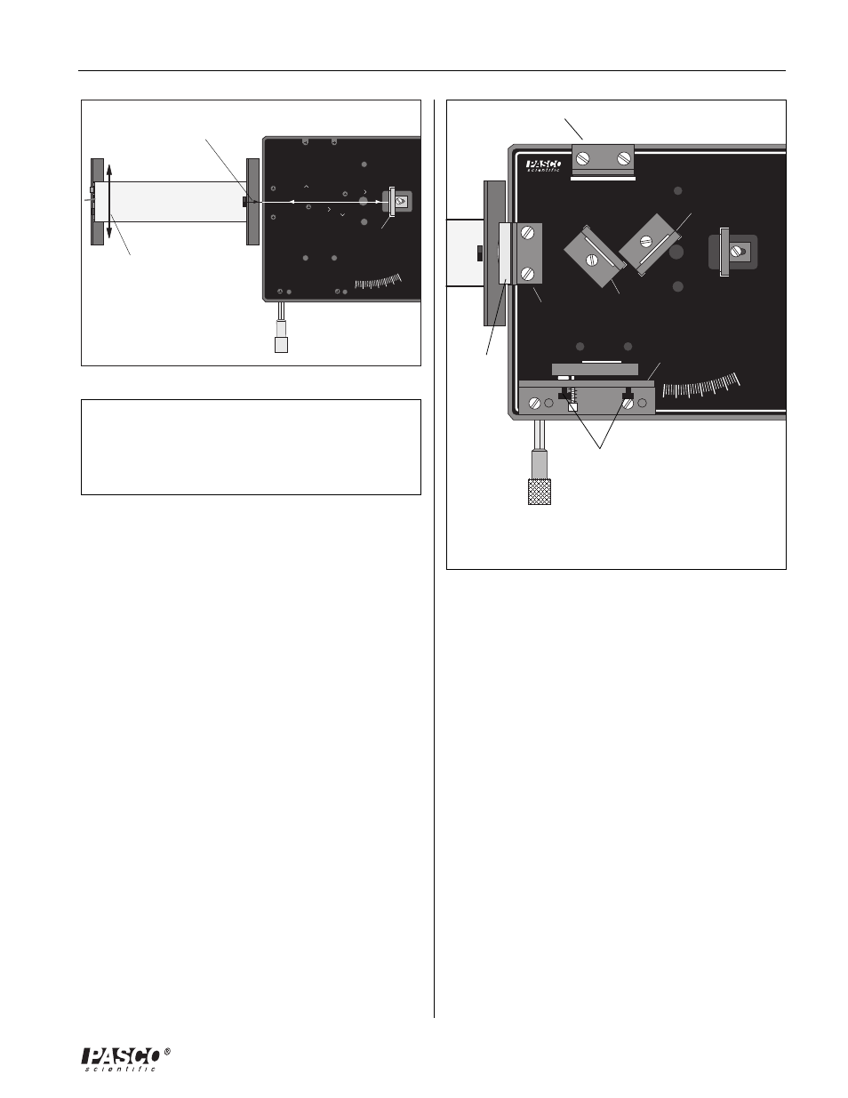
Slide the rear of the
laser laterally on the
alignment bench until
the beam is reflected
straight back into the
laser aperture.
Laser beam
Movable
mirror
Figure 5. Aligning the Laser
Michelson Mode
1.
Align the laser and interferometer base as previously
described. The laser beam should be approximately
parallel with the top of the base, should strike the center
of the movable mirror, and should be reflected directly
back into the laser aperture.
2.
Mount the adjustable mirror on the interferometer base.
Position one component holder in front of the laser.
Place the other component holder opposite the adjust-
able mirror and attach the viewing screen to its mag-
netic backing. See Figure 6.
3.
Position the beam-splitter at a 45 degree angle to the
laser beam, within the crop marks, so that the beam is
reflected to the fixed mirror. Adjust the angle of the
beam-splitter as needed so that the reflected beam hits
the fixed mirror near its center.
4.
There should now be two sets of bright dots on the
viewing screen; one set comes from the fixed mirror
and the other comes from the movable mirror. Each
set of dots should include a bright dot with two or more
dots of lesser brightness (due to multiple reflections).
Adjust the angle of the beam-splitter again until the two
sets of dots are as close together as possible, then
tighten the thumbscrew to secure the beam-splitter.
Component
holder
5.
Using the thumbscrews on the back of the adjustable
mirror, adjust the mirrors tilt until the two sets of dots
on the viewing screen coincide.
6.
The compensator is not needed for producing interfer-
ence fringes when using a laser light source. However,
if you wish to use the compensator, it mounts perpen-
dicular to the beam-splitter, as shown.
7.
Attach the 18 mm FL lens to the magnetic backing of
the component holder in front of the laser, as shown,
and adjust its position until the diverging beam is cen-
tered on the beam-splitter. You should now see circu-
lar fringes on the viewing screen. If not, carefully ad-
just the tilt of the adjustable mirror until the fringes ap-
pear.
8.
If you have trouble obtaining fringes, see Trouble-
Shooting at the end of this section.
Laser
Lens
18mm FL
Viewing screen
Component
holder
Beam
splitter
Movable
mirror
Compensator
(optional)
Adjustable mirror
Micrometer
knob
Interferometer
base
Thumbscrews
Figure 6. Michelson Mode Setup